13-25-607 Page 56
MINIMUM PRESSURE VALVE
Minimum Pressure Valve Inspection –
This device has no user-serviceable or repairable components.
If it fails to maintain adequate minimum pressure (70psig) or fails to check the backflow of system
compressed air after compressor stoppage, replace it as follows:
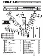
Figure 9- 4 - Minimum Pressure Valve and Seat
Air/oil pressure will cause severe personal injury or death. Shut down
compressor, relieve system of all pressure, disconnect, lockout and tagout
power supply to the starter before removing valves, caps, plugs, fittings, bolts
and filters.
1. Be sure the unit is completely off and that no air pressure is in the oil reservoir and in the air cooled
after cooler. Close the service valve.
2. Disconnect lockout and tagout the power supply to the starter.
3. Unscrew the minimum pressure valve assembly from compressor housing and remove.
4. Inspect the valve seat surface screwed into the compressor housing. Cleanse or replace - use 0.75"
hex wrench to unscrew. Note that fitting an o-ring on the hex wrench body helps hold the seat in
position during installation.
5. Assemble the minimum pressure check valve assembly into the housing.
6. Run the unit and check for leaks.
7. If a new minimum pressure valve has been fitted, its proper setting must be adjusted:
a. Make sure the site pipe system has a means to vent the compressor air to atmosphere with a
valve. If this is not available, temporarily fit a ½
” to ¾” ball valve to achieve so.
b. Start the compressor and monitor the wet
(B1)
and dry
(B2
) sump pressure sensors by
navigating the ASG2 controller display until displaying their pressure outputs.
c. Open the site vent valve to limit the dry sump pressure to about 40psig (2.8bar)
d. Remove the minimum pressure valve cover
– held in place by a screw. With a suitable tool
(needle-nose pliers will do), engage the two (2) small holes on the face of the adjusting disk
and turn clockwise until the wet sump reaches 70psig (4.8bar).
e. Replace the minimum pressure valve cover and securing screw.
f.
Close the site vent valve.
Содержание APEX15-18A
Страница 2: ......
Страница 11: ...13 25 607 Page 9 Figure 1 2 COMPRESSOR ILLUSTRATION EXTERNAL DETAILS 300UCC804 C Ref Drawing Page 1 of 1...
Страница 12: ...13 25 607 Page 10 Figure 1 3 COMPRESSOR ILLUSTRATION INTERNAL DETAILS 300UCC797 B Ref Drawing Page 2 of 2...
Страница 13: ...13 25 607 Page 11 Figure 1 4 COMPRESSOR ILLUSTRATION TOTAL SYSTEM 307UCC804 B Ref Drawing Page 1 of 1...
Страница 27: ...13 25 607 Page 25 Figure 4 2 WIRING DIAGRAM VS 200 460 VOLT 306UCC546 A Ref Drawing Page 1 of 4...
Страница 28: ...13 25 607 Page 26 Figure 4 3 WIRING DIAGRAM VS 200 460 VOLT 306UCC546 A Ref Drawing Page 2 of 4...
Страница 29: ...13 25 607 Page 27 Figure 4 4 WIRING DIAGRAM VS 200 460 VOLT 306UCC546 A Ref Drawing Page 3 of 4...
Страница 30: ...13 25 607 Page 28 Figure 4 5 WIRING DIAGRAM VS 200 460 VOLT 306UCC546 A Ref Drawing Page 4 of 4...
Страница 31: ...13 25 607 Page 29 Figure 4 6 WIRING DIAGRAM VS 575 VOLT 307UCC546 A Ref Drawing Page 1 of 4...
Страница 32: ...13 25 607 Page 30 Figure 4 7 WIRING DIAGRAM VS 575 VOLT 307UCC546 A Ref Drawing Page 2 of 4...
Страница 33: ...13 25 607 Page 31 Figure 4 8 WIRING DIAGRAM VS 575 VOLT 307UCC546 A Ref Drawing Page 3 of 4...
Страница 34: ...13 25 607 Page 32 Figure 4 9 WIRING DIAGRAM VS 575 VOLT 307UCC546 A Ref Drawing Page 4 of 4...
Страница 37: ...13 25 607 Page 35 Figure 4 10 PIPING AND INSTRUMENTATION ILLUSTRATION 301UCC797 F Ref Drawing...
Страница 60: ...13 25 607 Page 58 Figure 9 6 Compressor Module Hardware 308UCC810 C Ref Drawing Page 1 of 1...
Страница 69: ......


