background image

ITEM #05739 Rev B 

2


Содержание Genesis Series

Страница 1: ...erewith Next Day UPS Ground Under Separate Cover Second Day Air X Email FTP Site Hand Deliver Received by Date Time Hold for Pick Up Received by Date Time No of Copies Description Approved Approved as...

Страница 2: ...eturn corrected prints Not Approved Resubmit For bids due Remarks Copies to Field Superintendent Job Of ice File Architect Yours truly Owner CG Schmidt Inc r e P Flad Architects 644 Science Drive Madi...

Страница 3: ...GENESIS VERTICAL LIFT Enclosure Shaftway Models Owner s Manual Item 11301 Rev H...

Страница 4: ...the Lift 7 Manual Travel 8 Manual Lowering Handwheel Leadscrew Model Only 8 Manual Lowering Access Cap Leadscrew Model Only 8 Manual Lowering Hydraulic Model Only 9 Battery Powered Lowering Leadscrew...

Страница 5: ...ipment proper operation and periodic maintenance is required Important Please refer all service work to your Garaventa Lift dealer Garaventa dealers have the trained technicians with the required tool...

Страница 6: ...fferent accessibility challenges All versions of the Genesis Vertical Lift operate in the same manner and consist of a complete drive system a platform with side walls doors with an interlock system a...

Страница 7: ...Button Style Directional Switches Optional To use the illuminated call station buttons simply depress and hold the applicable arrow to call or send the platform 3 In Use Indication Lamp Optional The...

Страница 8: ...al Switches Optional To use the illuminated platform directional buttons simply depress and hold the applicable arrow to move the platform in the desired direction When the platform reaches the landin...

Страница 9: ...hands away from the hinged edge of the door when it is opening closing The swinging door may pinch fingers 4 Watch out for children when using the vertical lift 5 If you are using a wheelchair on the...

Страница 10: ...in the direction you wish to travel Remember that the switches are constant pressure and that the lift will stop moving as soon as you release the switch When you reach the next landing the platform...

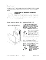
Страница 11: ...the top cover of the drive mast It is a domed cover which must be popped off so that the manual lowering handwheel can be inserted Make sure that the mains power is disconnected from the vertical lif...

Страница 12: ...he lowering device The knob then must be pulled to manually lower the platform Remote Installation Shaftway Model For shaftway applications the manual lowering device is shipped loose to allow the ins...

Страница 13: ...down direction only Auxiliary Power Standard on mains powered units Hydraulic Drive Model Only The auxiliary power system is automatically activated in the event of a power failure 12 Volt DC batterie...

Страница 14: ...rvice representative No Turn the call station key switch if equipped on Is the platform key switch if equipped turned on Turn the platform key switch if equipped on No Yes Call your Garaventa service...

Страница 15: ...s been jammed in any of the edges of the door Is a direction switch engaged Release the directional control Yes Is the platform really at the landing Move the platform 6 inches away from the landing a...

Страница 16: ...fety Nut Steel safety nut automatically engages if drive nut fails Platform falls less than when safety nut engages Engaging the safety nut trips the safety circuit Door Interlocks Door gate interlock...

Страница 17: ...Safety Features Safety Monitored slack chain device Automatically engages if the drive chain fails The platform falls less than when the slack chain safety device engages Door Interlocks Door gate in...

Страница 18: ...hat the life of your Garaventa Genesis will be extended Depending on the length of this agreement your warranty could be extended up to five years Remember to report any significant problems such as u...

Страница 19: ...y Transportation and labor charges are not covered Garaventa accepts no liability for any loss or damage resulting from use or misuse of the equipment whether such damage is direct indirect or consequ...

Страница 20: ...ITEM 05739 Rev B 1 Genesis Maintenance Manual This Manual covers Garaventa Genesis 2006 Model This Manual also includes information for Genesis 1...

Страница 21: ...ITEM 05739 Rev B 2...

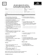
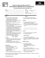
Страница 22: ...cklists There is one version each for Screw Drive and Hydraulic Drive Photocopy the forms and use them as a guide when performing a maintenance inspection Along with the suggested maintenance in the P...

Страница 23: ...es for these components Rust on the leadscrew This is a serious sign of neglect This is especially true if the rust can be seen in the travel area of the screw If you see this you must assume that the...

Страница 24: ...w and Nut engagement As the platform bottoms out on the floor you should not see the nut move relative to the screw On older lifts another method to check this is to remove the backside of the Nut it...

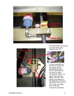
Страница 25: ...move the old one by unscrewing it from the piping Be ready to catch the grease that will come out once the threads are opened Take this grease and any grease around the Drive Nut and apply it to the e...

Страница 26: ...ITEM 05739 Rev B 7 The safety nut floats inside the support bracket This is critical to prevent binding and to ensure proper operation should the drive nut fail...

Страница 27: ...he grease canister screws directly into it Here the gap between the two nuts is also occupied by a plate The gap is then measured between the top of the plate and the bottom of the Safety Nut This mus...

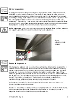
Страница 28: ...Interlock inspection The Garaventa solenoid lock is use don the vast majority of Garaventa Genesis lifts It includes a solenoid operated bolt that locks the doors closed when the lift is traveling Ins...

Страница 29: ...device on Genesis Hydraulic lifts is there to make sure any deviation from the normal travel of the support chains during travel does not result in an unsafe condition Whether one or both chains are s...

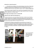
Страница 30: ...e the operation of the safety switch Inspection of landing limits This is a critical requirement in Genesis lifts and is often overlooked The test mainly pertains to the lower landing stopping locatio...

Страница 31: ...f the head is leaking the seals may be replaced Contact Garaventa Technical Support for parts and advice Inspection of the Chain Sprocket In Chained Hydraulic lifts the sprocket allows the chain to ru...

Страница 32: ...ntenance visit If a leak is found contact Garaventa Technical Support for advice on how to repair it Any cracked or broken pipes must be replaced Fittings may leak if they are subject to twisting or b...

Страница 33: ...bly to specified value correct Check the safety nut ___________________________________ Check Lubricator has sufficient grease capacity ___________________________________ Remaining approx ___________...

Страница 34: ...e level _________________________________ Does the slack rope device work at rated load _________________________________ Contact the factory for full test schedule Is the slack chain switch activated...

Страница 35: ...Genesis Repair Manual This Manual covers Garaventa Genesis I and Genesis 2006 Models ITEM 05751 Revision B Garaventa Lift April 2008 1...

Страница 36: ...is as of the print date of this document he main visible difference between the two models aside form the shipping ates is the shape of the mast Genesis I Models have an extra angles component the ma...

Страница 37: ...EMENT 20 REPLACING HARDWARE IN AN INTERNAL DOOR CLOSER 21 LATCH BLOCK UPGRADE APRIL 2008 22 OUT THIS MANUAL BLE OF CONTENTS 3 NESIS 2006 NESIS LEAD SCREW REMOVAL AND REPLACEMENT IVE NUT REPLACEMENT PR...

Страница 38: ...gs supplied in the kit into the drive nut halves and reinstall the Drive nut onto the screw checking that it is approximately 4 5 mm gap between it and the safety nut Refer to the picture attachment T...

Страница 39: ...ontinue to produce grease Be ready to catch the excess grease Smear it onto the drive e safety switch is properly positioned so that it will activate if the the screw ck its operation Return the lift...

Страница 40: ...tform walls and the platform Remove the mast covers and support the carriage so that you can access the Drive nut assembly easily Disassemble the Drive nut and Safety nut assembly See illustrations be...

Страница 41: ...upper nut This must be removed Back the Nut below down the screw before trying to remove the collar That nut is tight against the collar With the collar removed take the nut off the top end of the scr...

Страница 42: ...nd loosen the bottom bearing assembly screws There slider caps on each stabilizer block to be removed by The screw may now be removed in the direction away from the motor There are slots to allow you...

Страница 43: ...mage it and make it useless Make sure the pulley is in the proper position before installing the screw The pulley has a keyway and key that is retained by a setscrew Make sure this is tight Before fix...

Страница 44: ...0 007 00 Ca e e ure the greaser in installed properly and turned on and set to the appropriate ing rate See Tec ll T chnical Support at Garaventa if you have questions 1 800 667 7790 ITEM 05751 Revisi...

Страница 45: ...se Be ready to catch the excess grease Smear it onto the drive screw Turn the Lead screw so that it ascends above the nuts and their supporting frames in the cross member of the carriage Note the dist...

Страница 46: ...nits that are accessible behind the mast should provide easier access to the mast internals Im Drive screw rep the Safety Nut t installation of a new grease canister rts required th where a stab ow at...

Страница 47: ...ort the carriage so that you can access the Drive nu assembly easily Remove the mast cap look closely at the collar at the very top of the screw There is screw passing through the collar above the upp...

Страница 48: ...There emove the lower nuts on the screw ift the screw up until it clears the carriage at the bottom and then extract it out the front f the mast In units 96 and greater the stabilizer system must be...

Страница 49: ...rew retaining nuts apply a small amount of tension to the screw to the entire threads of the screw not just the travel rea heck the operation of the safety switch It must be adjusted as shown below A...

Страница 50: ...components in place Notice the gap between the safety nut and the support brackets above and below it The gap arrowed between the lower bracket and the Safety nut is about 5 6 mm ITEM 05751 Revision...

Страница 51: ...ed properly and turned on and set to the appropriate ispensing rate See Technical Bulletin 2000 007 00 all Technical Support at Garaventa if you have questions 1 800 667 7790 M d C ITEM 05751 Revision...

Страница 52: ...it to spill Remove entire cylinder and ram assembly from the mast to a clean area whe Remove the cylinder head and ram from the cylinder e the piston from the bottom end of the ram the Head Seal assem...

Страница 53: ...the lift is AW 32 weight hydraulic oil ESIS 2006 HYRAULIC LOWERING VALVE ACEMENT Ensure the work area is kept clean Ensure you have lots of rags ready to catch any oil spillag Raise the platform abov...

Страница 54: ...g connection at the valve Remove bracket for emergency lowering connection Use a 16mm wrench to remove the nut holding the valve cover in place and remove the valve cover black plastic Use a 22mm deep...

Страница 55: ...steps protruding from the door Allow the closer to retract to take the tension Release the connecting bolt in the door frame Loop wire through Put tension on the wire and remove the screwdriver or th...

Страница 56: ...repair is recommended This does not pertain to OPAL ed with mechanical locks shipped d t y ar from January 2007 to February 2008 and was a part of a let It is added to this manual as a reference docum...

Страница 57: ...orrection will not prevent the lift from stopping after two inches of travel if the platform moves away from the station without the door b s may be inconvenient for the user it does not creat Latch B...

Страница 58: ...haped side of the hole are is means the rounded edge and nding and face up at the upper Adjust the position of the block so the locking pin is approximately centered in the hole in the block and tight...

Отзывы: