Garaga CarGO 500 Скачать руководство пользователя страница 35

35

21. MAINTENANCE AND ADJUSTMENTS

To ensure continued safe operation and extended life of your operator system, periodic checking for proper operation is necessary. Occasional
maintenance and readjustment of your system may also be needed.

MONTHY:

• Check reversal system by performing

“safety reversal test” described in this manual.

• Check proper operation of door by manually

moving door open and closed. If door binds
or sticks, or is out of balance call for garag
door service.

• Check and test photo eye safety system as

described in this manual.

ONCE EVERY

YEAR:

• Keep door rollers,

hinges,and bearings
properly lubricated by
following recom-
mended door instruc-
tions or contacting a
door service company
in your area.

AS NEEDED:

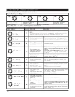
• Readjust operator travel limits and force settings as necessary —

due to cold weather, normal wear of door, etc. The convenient
adjustment instruction label on the operator can be used for any
periodic adjustments needed.

• Check and readjust belt tension, if necessary, in the unlikely event that

it loses its proper tension during the life of the operator. Always check
the reversal system after any adjustment of travel limits or forces. A
door operator that is not checked could possibly be out of adjustment
and be dangerous.

22. LIMITED PARTS WARRANTY

GARAGA INC.

PROFESSIONAL SERIES GARAGE DOOR OPERATOR SYSTEM

CarGo 700e Product Warranty — Parts Limited Lifetime on Operator & Rail

CarGo 500e Product Warranty — Parts 15 Year Warranty on Operator & Rail

*Labor Not Included in Warranties*

THIS LIMITED WARRANTY IS FOR THE ORIGINAL PURCHASER OF THE GARAGA UNIT

Coverage: THIS LIMITED WARRANTY IS FOR THE ORIGINAL PURCHASER OF THE GARAGA UNIT.

This Warranty applies, upon purchase from an authorized GARAGA reseller and installation by a professional installer and registration of the product within
14 days (or within 30 days of closing on a new home purchase from a developer) of the date of installation of the product, to any defect in materials or
workmanship in the GARAGA product parts or components from personal, normal household use in compliance with the Owner’s Manual. GARAGA
warrants this garage door opener system to its first retail, consumer purchaser. This is not a commercial product. GARAGA disclaims any and all warranties
in the event that the product is obtained from a source which is not a GARAGA authorized reseller or if the product is not installed by a professional installer.
“Grey market” and counterfeit purchases are not warranted or recognized in any manner whatsoever. This is not a “do it yourself” product. No “aftermarket”
installation, alteration, modification or repairs are recognized or warranted. Any of the foregoing conduct voids all warranty provisions. This warranty is for
parts only and is not for any service call(s) or labor in connection with the repair or replacement of the unit or its parts. Parts will only be shipped to your
GARAGA authorized reseller.

Pro-rated warranty on all materials:

The warranty will be complete the first year, and pro-rated for the following years according to the years left on

the warranty. The lifetime warranty on the CarGO 700e will be considered as twenty-five (25) years for pro-rating calculation purposes. The CarGO 500e will
be considered as fifteen (15) years for the pro-rating calculation purposes. The value of the warranty is calculated on the basic selling price given to the dealer
at the time of the claim.

GARAGA Commitment: 

If GARAGA determines the product parts to be defective in materials or workmanship, then GARAGA will supply parts for the

repair or replacement of the defect to the GARAGA authorized professional installer at no cost to you. You must pay for the service call and labor for
installation of the part(s) determined to be defective by GARAGA. At GARAGA’s sole option, GARAGA may elect to replace the part(s) with new or
reconditioned parts, components or units utilizing product of the same or similar design available at that given time.

THIS  LIMITED  WARRANTY  IS  IN  LIEU  OF  ANY  OTHER  WARRANTIES,  EXPRESS  OR  IMPLIED,  INCLUDING  ANY  IMPLIED
WARRANTIES OF MERCHANTABILITY OR FITNESS FOR A PARTICULAR PURPOSE, OR OTHER WARRANTIES IMPLIED BY STATUTE,
AND OF ANY OTHER OBLIGATIONS OR LIABILITY ON THE PART OF GARAGA INC. THIS LIMITED WARRANTY DOES NOT COVER
NON-DEFECT DAMAGE CAUSED BY IMPROPER INSTALLATION, OPERATION OR CARE AND MAINTENANCE, INCLUDING BUT NOT
LIMITED TO ABUSE, MISUSE, POWER SURGE, FAILURE TO PROVIDE REASONABLE AND NECESSARY MAINTENANCE OR ANY
ALTERATIONS  TO  THIS  PRODUCT,  INCLUDING  ACCESSORIES.  LABOR  CHARGES  FOR  DISMANTLING  OR  REINSTALLING  A
REPAIRED OR REPLACED UNIT ARE EXCLUDED.

GARAGA INC.’S LIABILITY IS EXPRESSLY LIMITED TO THE RETAIL COST OF THE PARTICULAR UNIT UNDER WARRANTY.

UNDER  NO  CIRCUMSTANCES  SHALL  GARAGA  INC.  BE  LIABLE  FOR  CONSEQUENTIAL,  INCIDENTAL  OR  SPECIAL  DAMAGES
ARISING IN CONNECTION WITH THE USE OR INABILITY TO USE THIS PRODUCT OR THE PREMISES IN WHICH IT IS UTILIZED. IN
NO EVENT SHALL GARAGA INC. INCUR LIABILITY FOR BREACH OF WARRANTY, BREACH OF CONTRACT, NEGLIGENCE OR STRICT
LIABILITY  IN  EXCESS  OF  THE  COST  OF  THE  PRODUCT,  INCLUDING  ACCESSORIES,  COVERED  HEREBY.  NO  PERSON  IS 
UTHORIZED TO ASSUME, FOR GARAGA INC., ANY OTHER LIABILITY OR MAKE ANY MODIFICATIONS OR EXTENSIONS TO THE
WARRANTY OF THIS PRODUCT. THIS LIMITED WARRANTY MAY NOT BE TRANSFERRED OR ASSIGNED.

Содержание CarGO 500

Страница 1: ......

Страница 2: ...LBS AND LENSES 16 8 14 CONNECT TO POWER 17 8 15 CONTROL PANEL 18 8 16 INITIAL SYSTEM SET UP 18 8 17 ADVANCED SETTING 20 8 18 TEST SAFETY REVERSAL 23 8 19 ALIGN AND TEST PHOTO EYE SENSORS 24 8 20 APPLY LABELS TO INSIDE OF GARAGE 25 8 21 ATTACH OWNER S MANUAL TO WALL 25 9 IMPORTANT SAFETY INSTRUCTIONS 25 10 TRANSMITTERS 26 11 OPERATION OF YOUR OPERATOR 27 12 HOMELINK TRANSCEIVER 27 13 MODULAR ANTENN...

Страница 3: ...nly the basic set up parameters All other operating parameters are learned and set automatically by the system In addition the system optimizes all parameters with every cycle for a more efficient operation by the GDO This shorter parameter set up provides a quicker and more efficient installation Precision Controlled DC Motor Complete with Automatic Soft Start and Soft Stop Feature The operator a...

Страница 4: ...ce supported by its springs Raise and lower the door fully to check for binding or sticking If door is out of balance or needs repair DO NOT ADJUST IT YOURSELF CALL A QUALIFIED GARAGE DOOR SERVICE PROFESSIONAL to adjust your door If your door is over 7 ft high you will need a longer rail see Fig 7 on page 6 Rail Assembly of this manual for availability of longer rails A garage door is a heavy movi...

Страница 5: ...all Header Bracket Highest Point of Door Distance Door Travel 1 1 4 Clearance Sectional Door with Curved Track Fig 3 Fig 4 5 GARAGE cont d Check the type of door construction you have The information contained in the figures below will be referred to later in the manual for proper installation on the different door types GARAGE DOOR OPERATOR SYSTEM OVERALL DIMENSIONS 7 DOOR ...

Страница 6: ...w 4 1 4 x 1 1 2 Drywall Anchors 2 Staples 10 30 ft 2 Conductor Wire Tapered Head Screws 2 Screw Caps 2 Machine screws 2 Header Bracket Door Bracket Warranty Card Rail Clip 2 Owner s Manuel Warning Operating Warning Label Garage Door Safety Label Support Bracket Fig 6 Power Head Accessories Models per application Belt Chain 7 Door ML 807B ML 807C 7 Door ML 808B ML 808C 7 Door ML 810B ML 810C Fig 7 ...

Страница 7: ... 6 Do not connect the operator to source of power until this manual instructs you to do so 7 Locate the wall control panel a within sight of door b at a minimum height of 5 feet above the ground so small children cannot reach it and c away from all moving parts of the door 8 Place the Operating Warning Label next to the wall control panel in a prominent location Affix Safety Label on inside of gar...

Страница 8: ...ed This way the appropriate brackets can be mounted at the correct locations avoiding installation and operating difficulties later MARK VERTICAL CENTER LINE Measure door width then locate the center point see Fig 9 Mark a vertical line on the upper half of your door on the top edge of your door and on the header through the center point MEASURE DOOR S HIGHEST TRAVEL POINT Review Figs on p 5 for d...

Страница 9: ...iling Header Bracket Lag Screw Pilot Hole Fig 11 8 3 INSTALL DOOR BRACKET TO DOOR Wood Sectional Doors Fig 13 Position door bracket see Fig 12 along vertical center line of door with pin hole facing top of the door and top edge of the bracket 4 to 5 below top edge of the door or roughly at the same height as top rollers on the door Mark locations of securement holes through door bracket Drill two ...

Страница 10: ...opener does not get scratched Chassis side of opener with motor shaft sticking out facing up Position rail onto operator chassis by lining up rail sprocket opening with motor head shaft see Fig 14A Make sure shaft engages teeth inside rail sprocket Press rail down firmly onto shaft and opener chassis DO NOT HAMMER Position 2 C rail clips over rail and onto chassis Flanges on C rail clips MUST fit ...

Страница 11: ...nsert header clevis pin 1 4 dia through header bracket and rail end stop then attach cotter ring to end of pin see Fig 19A 8 6 POSITION OPERATOR FOR MOUNTING Once rail is attached to header bracket support operator power head on ladder or use the assistance of another person to support operator high enough so door can open without hitting the rail Open garage door to fully opened position and plac...

Страница 12: ...ened in position remove wood blocks and temporary supports and lower door Check door for proper operation and clearance by manually moving door to full open and closed position If door hits rail at any point raise operator head slightly higher and re mount in position NOTE To provide additional support for 10 ft Doors and higher use the optional support bracket Accessories p 28 Measure the rail s ...

Страница 13: ...er door operation by manually lifting then lowering to fully opened and closed positions Readjust door arm if needed PULL DOWN ON RELEASE KNOB TO LOCK TROLLEY THEN MOVE DOOR MANUALLY UNTIL TROLLEY LOCKS WITH CHAIN OR BELT CONNECTOR 8 9 CHECK EMERGENCY RELEASE The emergency release cord with red knob which is already attached to the trolley are extremely important parts of the operator system see F...

Страница 14: ...ch the sensor cap and the sensor cap fastener to the bracket Secure the photo eye sensor to the bracket with fastening wheel Repeat process for the other sensor MOUNTING THE PHOTO EYE SENSOR BRACKETS TO WALL Locate the mounting position for brackets bracket can be mounted in any position as long as photo eye beam will have a clear path from one side of door to the other side after mounting Use the...

Страница 15: ...Do not pinch wiring Drive staples with only enough force to hold wiring in place Refer to Fig 8 on p 7 for an example of typical wiring routing and Fig 26 for terminal assignment NOTE As an alternative for photo eye system the wiring can be routed along the top of the rail or along the outside of the door track Be sure the wiring is routed away from all moving parts of the door and rail Separate 2...

Страница 16: ...lots Chassis Slots Lens Tabs housing Lens Tabs chassis Chassis Slots Housing Slots Install Bulb Snap lamp lens tabs into slots in chassis Hinge lamp lens downward line up tabs with slots in housing and snap into place Standard incandescent light bulb 60W max Lens Tabs chassis Standard incandescent light bulb 60W max Fig 27 Warning To prevent possible serious injury and damage to the operator when ...

Страница 17: ...over so that after cut there is at least 6 of wiring remaining Remove approx 1 of black insulation left on the cable to expose the three conductor leads white neutral black hot and green ground Remove screw and unsnap the power cord strain relief cover by disengaging the tabs and remove this part save for reattachment later Remove the cut power cord and discard Replace the strain relief cover by s...

Страница 18: ...imply enter the adjustment mode by pressing and holding the P button for pproximately 5 seconds then press and release P repeatedly until your particular adjustment is reached This bypasses the unneeded adjustments and takes you right to the adjustment you want When your adjustment or setting is complete simply press P as many times as needed to bypass the remaining steps and exit out of the progr...

Страница 19: ... using and 1 5 3 7 2 4 6 8 1 5 3 7 2 4 6 8 7 P 1x 1s Save the CLOSED door position Program the transmitter code to GDO 1 5 3 7 2 4 6 8 8 Press the transmitter button LED 7 flashes rapidly 1 5 3 7 2 4 6 8 9 Release the transmitter button 1 5 3 7 2 4 6 8 10 P 1x 1s Save the transmitter code settings End the system setup programming procedure 1 5 3 7 2 4 6 8 1 5 3 7 2 4 6 8 Operating mode Legend LED ...

Страница 20: ...nu 1 Menu Exit Level 2 Menu 2 Menu 3 Menu 8 Parameter Increase value Reduce value P P P Level 1 5 sec P 5 sec P Continue to levels 5 6 7 Levels 3 4 6 7 are disable P P Operating mode End programming Additional operator functions can be set using the expanded operator functions Important factory default settings can be changed there This rogramming may only be carried out by professional installer ...

Страница 21: ...General overview of the programmable functions Level 1 Functions overview NOTE Menus 1 2 and 7 are disabled Press or button to scroll or navigate through menus Level 1 1 2 3 4 5 6 7 8 9 10 11 12 13 14 15 16 Menu 5 Soft run position OPEN Set using the OPEN and CLOSE buttons Menu 6 Soft run position CLOSE Set using the OPEN and CLOSE buttons Menu 8 RESET No Yes CAUTION After a system reset all param...

Страница 22: ...losing edge safety device is installed Note The higher the setting the higher the driving power or more sensitive operation Menu 2 Required driving power to CLOSE sensitivity on a scale from 1 to 16 1 2 3 4 5 6 7 8 9 10 11 12 13 14 15 16 Menu 3 Automatic cut out OPEN sensitivity on a scale from 1 to 16 OFF 2 3 4 5 6 7 8 9 10 11 12 13 14 15 16 Menu 4 Automatic cut out CLOSE sensitivity on a scale f...

Страница 23: ...un up and down twice to learn the new settings you must test the reversal system for proper operation Place a 1 1 2 high rigid object or a 2x4 board laid flat on the floor directly in the path of the door see Fig 32 Start the door in the downward direction and watch what happens When door contacts the object or 2x4 it should stop reverse and automatically return to the fully opened position If the...

Страница 24: ...ht Mount the transmitter TX sensor on the side which is exposed to the most sun Sunlight may affect the Safety Sensors and this orientation will help reduce the effect SAFETY TEST Photo eye sensors installed on opposite sides of your door opening are intended to detect a person or object in the path of the door and prevent the door from moving downward The following steps will determine if the sys...

Страница 25: ...NSTRUCTIONS CAREFULLY 2 Never let children operate or play with door controls Keep the remote control away from children 3 Always keep the moving door in sight and away from people and objects until it is completely closed NO ONE SHOULD CROSS THE PATH OF THE MOVING DOOR 4 NEVER GO UNDER A STOPPED PARTIALLY OPEN DOOR 5 Test door operator monthly The garage door MUST reverse on contact with a 1 1 2 ...

Страница 26: ...ght in the transmitter initially starts blinking and then illuminates continuously after 1 2 sec Code transfer is completed Programming connector can be removed and both transmitters can now be used to operate the same opener NOTE For multi button transmitters be sure to carry out this procedure for all the buttons you desire to use CHANGING THE CODE Fig 39 The transmitter factory preset code can ...

Страница 27: ...ctivated by wall control panel or keyless entry system Press and hold Lock Vacation button for 2 3 seconds Release button Illuminated Door Pushbutton will flash continuously while lock mode is active To unlock opener press and hold Lock Vacation button for 2 3 seconds OPERATOR LIGHTS The amount of time that the operator light s are on can be adjusted Please refer to level 5 menu 4 in the Advanced ...

Страница 28: ...BY A PROFESSIONAL INSTALLER FULLY FAMILIAR WITH THIS TYPE OF OPENER SYSTEM TO SHORTEN BELT RAIL LENGTH Loosen belt tension as much as possible Remove screws from sprocket holder and rail end stop Slide belt and all rail parts out of rail from header end See rail exploded view Fig 46 on p 29 for disassembly details Measure and cut off excess rail from header end Using rail end stop as a guide mark ...

Страница 29: ...ley assembly 7 Door 8030178 Trolley assembly 8 10 Door 9 8008708 Pin 10 8030735 Straight door arm 11 8007412 Shaft adapter 1 2 10 7 5 3 4 Header End 9 8 Chain Rail Assembly Model ML 807C 7 Door ML 808C 8 Door ML 810C 10 Door Power Head End 6 Fig 47 Item Partie Description Item Partie Description 1 Rail 2 8030339 Sprocket holder assembly 3 8030432 Roller holder with tension bolt assembly 4 8008503 ...

Страница 30: ...5 16 17 18 19 20 21 80349 80348 83329 78936 8054389 79903 8007776 73557 73109 78914 79011 78938 70014 78236 78157 73699 72784 8055529 73894 60379 Lamp Lens Lamp Lens Housing Assembly Chassis Wire Harness Reference Switch Power Cord Strain Relief Cover Ribon Cable Ribon Cable Logic Board Control Panel Terminal Board Terminal Board Housing Modular Receiver Transformer Wire Harness Motor Transformer ...

Страница 31: ...13 14 15 16 17 18 19 20 21 80350 83328 78724 8054389 8030987 79903 73557 73109 78914 79011 78938 70014 78236 78156 73699 72784 8055529 73894 60379 Lamp Lens Housing Assembly Chassis Wire Harness Reference Switch Power Cord Strain Relief Cover Ribon Cable Ribon Cable Logic Board Control Panel Terminal Board Terminal Board Housing Modular Receiver Transformer Wire Harness Motor Transformer Power Boa...

Страница 32: ...RO 3 Channel Model M3 3313CG Photo Eye Safety System Provides a system of protection for you and your family Designed to suit your particular garage Model M4 705 Lens Sunshield Extension Part 73536 Extension Bracket Kit Hardware included Part 72802 Support Bracket Helps support rails for 10 doors and higher Part 71865 Mounting Plate MINI Model ML 920 Wireless Keyless Entry System Permits control o...

Страница 33: ...ent mais qu elle ne ferme plus complètement modifiez la limite de fermeture et ou augmentez la force descendante pages 14 et 24 UNE FOIS TERMINÉ RÉPÉTEZ LE PROCÉDÉ VÉRIFICATION DU SYSTÈME D INVERSION AUTOMATIQUE page 23 Door opens but will not close at all LED 1 ON Check photo eye sensor wires connections to the operator terminals Refer to pages 14 and 24 LED 1 Blinks Check sensor alignment and se...

Страница 34: ...roken springs Clear obstructions or have door serviced If door is OK increase force setting REPEAT THE SAFETY REVERSAL TEST page 23 AFTER ADJUSTMENT IS COMPLETE Vérifiez la force maximale programmée Voir programmation avancée page 22 Menu 1 et 2 7 Flashes 8 Flashes 1 8 Flashes 2 8 Flashes 3 8 Flashes 7 8 Flashes 1 7 8 Flashes 5 6 7 8 Flashes 11 Operator exceeded maximum run time limit Make sure ra...

Страница 35: ...aftermarket installation alteration modification or repairs are recognized or warranted Any of the foregoing conduct voids all warranty provisions This warranty is for parts only and is not for any service call s or labor in connection with the repair or replacement of the unit or its parts Parts will only be shipped to your GARAGA authorized reseller Pro rated warranty on all materials The warran...

Страница 36: ...onditions and void all warranties This would violate the UL Safety Approval of the product and constitute a safety hazard This Limited Warranty contains the entire warranty on the product All discussions representations or negotiations between the consumer and the retail seller are merged into this Limited Warranty and there are no understandings or warranties other than those herein None of the t...

Отзывы: