GAPOSA QCzero Скачать руководство пользователя страница 60

60

QCzero QCzeroP

GAPOSA srl - via Ete, 90 - 63900 Fermo - Italy

T. +39.0734.22071 - F. +39.0734.226389 - [email protected]

www.gaposa.com

QC0_230V_I_ML_0411

Certified Quality System

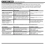
CONDIZIONI GENERALI DI VENDITA

Poiché  i  nostri  prodotti  sono  soggetti  a  continue  innovazioni  e  miglioramenti,  le  caratteristiche  costruttive  possono  subire 

variazioni anche senza preavviso. La nostra società si riserva di riparare o sostituire presso la nostra sede, gratuitamente, tutte 

quelle parti riconosciute come difettose nella fabbricazione, a nostro insindacabile giudizio, durante il periodo di garanzia del 

prodotto. La garanzia ha validità 24 mesi dalla data di collaudo impressa sul prodotto.

I  prodotti  da  riparare  dovranno  essere  resi  in  PORTO  FRANCO  alla  ns.  Sede  e  saranno  rispediti  in  PORTO  ASSEGNATO.  Ogni 

manomissione o modifiche non autorizzate ed il non rispetto delle istruzioni e delle norme di installazione vigenti, rendono 

decaduta  la  garanzia.  La  garanzia  viene  a  cessare  se  il  cliente  non  è  in  regola  con  i  pagamenti.  La  società  declina  ogni 

responsabilità dovuta alla inosservanza delle norme di sicurezza da parte dell’installatore

GENERAL SALE CONDITIONS

As our products can benefit from continuos innovations and improvements, their building features can be modified without any 

warning. Our society will repair or replace free of charge all those components which we will judge as a factory defect during the 

product’s warranty period. The warranty has a 24 months validity time from the testing date shown in the product. The products 

to be repaired must be sent to our warehouse at our customer’s charges and will be sent back as ex-works. No warranty will 

be recognized for any improper use/installation, unauthorized modifications or the non respect of the instructions and of the 

current installation laws. The warranty will also expire if the customer doesn’t respect the payment terms. The company declines 

every responsibility due to the installer’s non-observance of the safety norms.

CONDITIONS GENERALES DE VENTE

Etant  nos  produits  sujets  a  de  continuelles  innovations  et  améliorations,  leurs  caractéristiques  constructives  peuvent  subir 

des variations même sans préavis. Notre société se réserve le droit de réparer ou remplacer chez nous gratuitement  toutes 

les  partie  reconnues  comme  défectueuses  à  causes  d’un  défaut  de  fabrication  ,  de  notre  incontestable  avis,  pendant  la 

période de garantie du produit. La garantie a validité 24 mois à partir de la date d’essai marqués sur le produit. Les produits 

qu’il  faut  réparer  devront  être  retournés  PORT  FRANC  chez  nous  et  seront  renvoyés  PORT  DÛ.  Chaque  manumission  ou 

modification  non  autorisée  et  le  non  respect  des  notices  et  des  normes  d’installation  en  vigueur,  rendent  la  garantie  nulle. 

La garantie cesse si le client n’est pas en règle avec les payements. La société décline toute responsabilités dues au non respect 

des normes de sécurité de la part de l’installateur.

CONDICIONES GENERALES DE VENTA 

Ya  que  nuestros  productos  están  sujetos  a  continuas  innovaciones  y    actualizaciones,  las  características  constructivas 

pueden sufrir variaciones también sin preaviso. Nuestra sociedad se reserva la opción de reparar o sustituir , gratuitamente, 

todas  las  partes  que  se  reconozcan  defectuosas  en  la  fabricación,  a  nuestro  inapelable  juicio,  durante  el  periodo  de 

garantía  del  producto.  La  garantía  tiene  una  validez  de    24  meses  de  la  fecha  de  prueba  impresa  en  el  producto.  Los 

productos  para  reparar  deberán  ser  devueltos  a  portes  pagados  a  nuestra  empresa  y  serán  reenviados  a  portes  debidos. 

Cualquier  manipulación  o  modificaciones  no  autorizadas  y/o  el  incumplimiento  de  las  instrucciones  y  de  las  normas  de 

instalación  vigentes,  anulan  automáticamente  la  garantía.  La  garantía  cesa  si  el  cliente  no  está  a  regla  con  los  pagos.  

La sociedad declina toda responsabilidad derivada de la incumplimiento de las normas de seguridad por parte del instalador.

Содержание QCzero

Страница 1: ...p 32 p 46 Centrale di comando con ricevitore integrato Istruzioni Control unit with integrated receiver Instructions Armoire de commande avec r cepteur integr Instructions Central de mando con recepto...

Страница 2: ...supply is cut off TURN THE MAIN SWITCH OFF before any other operation Queste istruzioni contengono delle importanti informazioni sull istallazione e l uso della centrale QC0 QC0P Conservatele sempre...

Страница 3: ...ranchements doivent tre effectu s seulement une fois l alimentation principale d connect e COUPER l interrupteur G N RAL avant toute op ration Estas instrucciones contienen importantes informaciones s...

Страница 4: ...PER COMANDO A 3 TASTI 3 4 1 PROGRAMMAZIONE TASTO APRI 3 4 2 PROGRAMMAZIONE TASTO CHIUDI 3 4 3 PROGRAMMAZIONE TASTO STOP 3 5 PROGRAMMAZIONE CODICI LAMPADA DI CORTESIA 3 6 CANCELLAZIONE TRASMETTITORI D...

Страница 5: ...con ricevitore radio 1 UP PH TEST LIGHT ANT ON ED ST SS DW 2 3 4 5 6 7 8 9 10 11 12 13 14 15 16 17 18 19 20 21 22 23 1 ON 2 3 4 5 6 7 8 9 10 M UP START STOP EDGE COM COM COM FLASH DOWN STOP PHOTO MAX...

Страница 6: ...ti 8 9 1 2 3 4 5 6 7 8 9 10 12 13 14 15 M 16 17 18 19 20 21 UP START STOP EDGE COM COM COM FLASH DOWN STOP PHOTO MAX 40 W TEST 24 Vac AUX 230 V 230Vac 50 60Hz C L N 11 MORSETTO DESCRIZIONE MORSETTO DE...

Страница 7: ...ti dell alimentazione 24 Vac 10 11 e dei contatti 7 8 e 9 devono essere completamente separati 1 2 1 FOTOCELLULE TRADIZIONALI CON CONTATTO NORMALMENTE CHIUSO PULSANTE FUNZIONE MORSETTI DI COLLEGAMENTO...

Страница 8: ...rsi al manuale delle fotocellu le utilizzate L alimentazione delle fotocellule riceventi separata da quella delle trasmittenti e va prelevata all uscita 24Vac della centrale Non necessario rispettare...

Страница 9: ...in OFF Come comando di accensione di impianti di illuminazione ad ogni apertura se il dip 5 della scheda in ON L uscita del contatto ai morsetti 13 e 14 AUX ATTENZIONE Si pu collegare al massimo un ca...

Страница 10: ...entrale pu essere comandata via radio permettendo la memorizzazione di 63 codici radio PROGRAMMAZIONE TRASMETTITORI Quando si programmano occorre mantenerli ad una distanza di almeno 50 cm dalla centr...

Страница 11: ...p 7 in ON i dip 9 e 10 devono stare in OFF 2 Inviare il codice radio da memorizzare 3 Il led TEST esegue 1 lampeggio se il codice stato memorizzato 3 lampeggi se gi presente in memoria Quando la memor...

Страница 12: ...mente importante verificare il verso del motore e la posizione dei finecorsa Se le fasi del motore sono invertite anche i sistemi di sicurezza hanno di un funzionamento invertito creando una situazion...

Страница 13: ...i di sicurezza viene fermato il movimento del motore 2 Posizionare la porta a met corsa Mettere i dip 1 e 2 in OFF e poi il dip 6 in ON 3 Dare un comando SS 1 la porta inizier ad aprirsi Quando arriva...

Страница 14: ...a fotocellula inverte il movimento della porta in apertura FUNZ IN CHIUSURA ED IN APERTURA mettere il dip 3 in ON durante la chiusura l intervento della fotocellula inverte il movimento della porta Du...

Страница 15: ...te resistive con contatto da 8K2 4 5 LOGICA LAMPADA DI CORTESIA Il contatto della lampada di cortesia pu avere 2 modi di funzionamento OPERAZIONI 1 Posizionare in ON il dip 6 della centrale 2 Commutar...

Страница 16: ...Indica lo stato dell ingresso CHIUDI mors 2 3 SS Indica lo stato dell ingresso Start Stop mors 4 5 ST Indica lo stato dell ingresso STOP mors 5 6 ED Indica lo stato della COSTA mors 7 8 Quando la cos...

Страница 17: ...usibile Fuse2 Sono rimasti in ON i dip 6 7 8 9 o 10 Posizionare in OFF i dip 6 7 8 9 10 La porta si muove solo in apertura La fotocellula F1 guasta o occupata il led F1 spento Verificare lo stato dell...

Страница 18: ...G OF THE OPEN BUTTON 3 4 2 PROGRAMMING OF THE CLOSE BUTTON 3 4 3 PROGRAMMING OF THE STOP BUTTON 3 5 PROGRAMMING OF THE COURTESY LIGHT CODE 3 6 REMOVE TRANSMITTERS FROM THE MEMORY 3 7 PROGRAMMING WORKI...

Страница 19: ...ntegrated receiver 1 UP PH TEST LIGHT ANT ON ED ST SS DW 2 3 4 5 6 7 8 9 10 11 12 13 14 15 16 17 18 19 20 21 22 23 1 ON 2 3 4 5 6 7 8 9 10 M UP START STOP EDGE COM COM COM FLASH DOWN STOP PHOTO MAX 40...

Страница 20: ...18 19 20 21 UP START STOP EDGE COM COM COM FLASH DOWN STOP PHOTO MAX 40 W TEST 24 Vac AUX 230 V 230Vac 50 60Hz C L N 11 CONNEC TION TERMINALS DESCRIPTION CONNEC TION TERMINALS DESCRIPTION 1 UP N O 10...

Страница 21: ...e completely separated 1 2 1 SAFETY BEAMS with normally closed contact PUSHBUTTONS FUNCTION CONNECTION TERMINALS UP Normally open Shutter s opening Must be linked to terminals 1 up and 2 com DOWN Norm...

Страница 22: ...e termi nals 10 and 12 TEST POWER SUPPLY RECEIVERS refer to the instructions booklet of the safety beams in use The power supply of the receivers safety beam is separated by that of the receiving one...

Страница 23: ...gnition control for lighting systems at every opening when the board s dip 5 is in ON position The contact s output is at the terminals 13 and 14 AUX ATTENTION Max loading capacity is 5A at 230 Vac 2...

Страница 24: ...QCTSE2 QCTSE4 The control unit can be controlled via radio and 63 radio codes can be memorized TRANSMITTERS PROGRAMMING When programming the transmitters it is necessary to keep them at a 50 cm dista...

Страница 25: ...on dip 9 and 10 must remain in OFF position 2 Send the radio code to be memorized 3 The TEST led makes 1 flash if code has been memorized or it flashes 3 times if already memorized previously when mem...

Страница 26: ...solutely important to verify the motor s direction and the limit switch position If the motor s lines are inverted the safety devices will have an inverted activity as well creating in this way a DANG...

Страница 27: ...safety devices then the motor stops 2 Place the door at half way Place the dip 1 and 2 in OFF position and then dip 6 in ON position 3 Give a START STOP SS signal the door starts to open When opening...

Страница 28: ...ts the movement of the opening door FUNCTION DURING CLOSURE AND OPENING place the dip 3 in ON position while closing the safety beam s activity inverts the movement of the door while opening the safet...

Страница 29: ...ontact 4 5 COURTESY LIGHT LOGIC The courtesy light contact can have 2 working modalities OPERATIONS 1 Place in ON position the control unit s dip 6 2 Switch for at least 3 times the dip3 in ON and OFF...

Страница 30: ...tus of the OPEN terminal terminals 1 2 DW It shows the status of the CLOSE terminal terminals 2 3 SS It shows the status of the Start Stop terminal terminals 4 5 ST It shows the status on the STOP ter...

Страница 31: ...Place the Dip 6 7 8 9 and 10 in OFF position The door moves only in the opening direction The safety beam F1 is damaged or busy led F1 is off Verify the status of the safety beam see page 21 Remove a...

Страница 32: ...MMATION TOUCHE OUVRIR 3 4 2 PROGRAMMATION TOUCHE FERMER 3 4 3 PROGRAMMATION TOUCHE STOP 3 5 PROGRAMMATION CODES DE LA LAMPE DE SERVICE 3 6 EFFACEMENT METTEURS DE LA M MOIRE 3 7 PROGRAMMATION TEMPS DE...

Страница 33: ...motor ducteurs monophas s 1 UP PH TEST LIGHT ANT ON ED ST SS DW 2 3 4 5 6 7 8 9 10 11 12 13 14 15 16 17 18 19 20 21 22 23 1 ON 2 3 4 5 6 7 8 9 10 M UP START STOP EDGE COM COM COM FLASH DOWN STOP PHOTO...

Страница 34: ...ule bornes 8 9 1 2 3 4 5 6 7 8 9 10 12 13 14 15 M 16 17 18 19 20 21 UP START STOP EDGE COM COM COM FLASH DOWN STOP PHOTO MAX 40 W TEST 24 Vac AUX 230 V 230Vac 50 60Hz C L N 11 BORNES DESCRIPTION BORNE...

Страница 35: ...ntation 24 Vac 10 11 e des borniers 7 8 9 doivent tre completement s par s 1 2 1 PHOTOCELLULES TRADITIONNELLES AVEC CONTACT NORMALEMENT FERM BOUTON FONCTION BORNES DE BRANCHEMENT MONTEE Normalement ou...

Страница 36: ...ON RECEPTEURS Il faut faire r f rence au manuel des photocellules utilis es L alimentation des photocellules r ceptrices est s par e de celle des mettrices et doit tre pr lev e la sortie 24Vac de l ar...

Страница 37: ...commande d allumage de syst mes d clairage chaque ouverture si le dip 5 de la carte est en ON La sortie du contact est aux bornes 13 et 14 AUX ATTENTION On peut brancher au maximum une charge de 5A 23...

Страница 38: ...O QCTE QCTSE2 QCTSE4 L armoire peut tre command e par radio permettant la m morisation de 63 codes radio PROGRAMMATION EMETTEURS Lorsqu on les programme il faut les tenir une distance d au moins 50 cm...

Страница 39: ...2 Envoyer le code radio qu il faut m moriser 3 Le led TEST clignote 1 fois si le code a t m moris ou clignote 3 fois s il est d j pr sent dans la m moire Lorsque la m moire est pleine et il n est plus...

Страница 40: ...osition des fins de courses Si les phases du moteur sont invers es les syst mes de s curit auront galement un fonctionnement invers en cr ant une situation de DANGER OPERATIONS Ex cuter la proc dure P...

Страница 41: ...curit sont actionn s le mouvement du moteur est arr t 2 Positionner la porte mi course Mettre les dip 1 et 2 en OFF et puis le dip 6 en ON 3 Donner une commande SS la porte commence s ouvrir Quand la...

Страница 42: ...ention de la photocellule invertit le mouvement de la porte en ouverture FONCTION EN FERMETURE mettre le dip 3 en OFF pendant la fermeture l intervention de la photocellule invertit le mouvement de la...

Страница 43: ...lement ferm et aussi des barres r sistives avec contact 8K2 4 5 LOGIQUE LAMPE DE SERVICE Le contact de la lampe de service peut avoir 2 modes de fonctionnement OPERATIONS 1 Positionner en ON le dip 6...

Страница 44: ...Indique l tat de l entr e FERMER bornes 2 3 SS Indique l tat de l entr e Start Stop bornes 4 5 ST Indique l tat de l entr e STOP bornes 5 6 ED Indique l tat de la BARRE bornes 7 8 Lorsque la barre es...

Страница 45: ...ip 6 7 8 9 ou 10 sont rest s en ON Positionner en OFF les dip 6 7 8 9 10 La porte s ouvre seulement en ouverture La photocellule F1 est en panne ou occup e le led F1 est teint V rifier l tat de la pho...

Страница 46: ...DORES 3 4 1 PROGRAMACION PULSADOR SUBIDA 3 4 2 PROGRAMACION PULSADOR BAJADA 3 4 3 PROGRAMACION PULSADOR STOP 3 5 PROGRAMACION CODIGOS LUZ INTERMITENTE 3 6 CANCELACION DE LOS TRASMISORES EN MEMORIA 3 7...

Страница 47: ...on receptor radio 1 UP PH TEST LIGHT ANT ON ED ST SS DW 2 3 4 5 6 7 8 9 10 11 12 13 14 15 16 17 18 19 20 21 22 23 1 ON 2 3 4 5 6 7 8 9 10 M UP START STOP EDGE COM COM COM FLASH DOWN STOP PHOTO MAX 40...

Страница 48: ...6 7 8 9 10 12 13 14 15 M 16 17 18 19 20 21 UP START STOP EDGE COM COM COM FLASH DOWN STOP PHOTO MAX 40 W TEST 24 Vac AUX 230 V 230Vac 50 60Hz C L N 11 BORNES EXPLICACION BORNES EXPLICACION 1 UP MONTEE...

Страница 49: ...s de la alimentaci n 24 Vac 10 11 y de los contactos 7 8 y 9 deben estar completamente separadas 1 2 1 FOTOC LULAS TRADICIONALES CON CONTACTO NORMALMENTE CERRADO PULSADOR FUNCION BORNES DE CONEXION SU...

Страница 50: ...de los dos cables Deben ser conectados a los bornes 10 y 12 TEST ALIMENTACION RECEPTORES Referencia en el manual de las fotocelulas utilizadas La alimentaci n para las fotoc lulas emisoras esta separ...

Страница 51: ...e la central en posici n OFF La l mpara se encender en apertura colocando el dip 5 de la central en posici n l ON Se debe conectar a los bornes 13 e 14 AUX Se puede conectar una carga m xima de 5A a 2...

Страница 52: ...r comandada por radio y permite la memorizaci n de 63 c digos radio PROGRAMACION TRANSMISORES Cuando se programan se les debe dejar a una distancia de al menos 50 cm de la central Asi se evitan fen me...

Страница 53: ...ON los dip 9 e 10 deber ser en OFF 2 Enviar el c digo radio que se debe memorizar 3 El led TEST destella 1 vez si el c digo ha sido memorizado o 3 veces si el c digo esta ya est en memoria Cuando la m...

Страница 54: ...rtante verificar el sentido del motor y la posicion de los finales de carrera Si las fases del motor son invertidas los sistemas de seguridad tambien funcionar n invertidos y crear n una situaci n de...

Страница 55: ...os finales de carrera est n ajustados Si durante el procedimiento intervienen sistemas de seguridad el movimiento del motor se para 2 Posicionar la puerta a media altura Poner los dip 1 y 2 en OFF y d...

Страница 56: ...cierre la intervenci n de la fotoc lula invierte el movimiento de la puerta en apertura FUNCION EN CIERREY EN APERTURA poner el dip 3 en ON durante el cierre la intervencion de la fotoc lula invierte...

Страница 57: ...sistivas con contacto de 8K2 4 5 L GICA L MPARA DE CORTES A El contacto de la lampara de cortes a puede tener dos modalidades de funcionamiento OPERACIONES 1 Poner en ON el dip 6 de la central 2 Conmu...

Страница 58: ...el ingreso CERRAR bornes 2 3 SS Indica el estado del ingreso Start Stop bornes 4 5 ST SI ESTA ENCENDIDO Indica el estado del ingreso STOP bornes 5 6 ED Indica el estado de la BARRA bornes 7 8 Cuando l...

Страница 59: ...dip 6 7 8 9 o 10 Poner en OFF los 6 7 8 9 10 La puerta se mueve solamente en apertura Si la fotoc lula F1 est averiada u ocupada el led F1 est apagado Verificar el estado de la fotoc lula Despejar los...

Страница 60: ...r doesn t respect the payment terms The company declines every responsibility due to the installer s non observance of the safety norms CONDITIONS GENERALES DE VENTE Etant nos produits sujets a de con...

Отзывы: