background image


Network Video Recorder 

User Manual 


Issue: V1.0 (2016-01-20) 


37 


Parameter 

Description 

Setting 

Account 

User name for logging in to the 
DDNS server. 

[Setting method] 

Enter a value manually. 

[Default value] 

Blank 

Password 

Password for logging in to the 
DDNS server. 

[Setting method] 

Enter a value manually. 

[Default value] 

Blank 


Step 3


Click 

Apply


If the message "Apply success" is displayed, click 

OK

. The system saves the 

settings. 


If other information is displayed, set the parameters correctly. 

-     

PPPoE 

Obtain the PPPoE user name and password from the network carrier. 

Step 1


Choose 

Setup

 > 

NVR Setup

 > 

Network Service

 > 

PPPoE

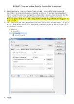
The PPPoE page is displayed, as shown in Figure 7-13. 

Figure 7-13


The 

PPPoE

 interface 


Step 2


Click the button on to enable 

PPPoE

. Set the parameters according to Table 7-5. 

Содержание ZN8 Series

Страница 1: ...ZN8 Series NVR IP network recorder User manual Version 1 0 Date 20 01 2016 ...

Страница 2: ......

Страница 3: ... avoided result in moderate or minor injury Alerts you to a potentially hazardous situation that could if not avoided result in equipment damage data loss performance deterioration or unanticipated results Provides a tip that may help you solve a problem or save time Provides additional information to emphasize or supplement important points in the main text Important Statement Users are required ...

Страница 4: ...2 Shutdown 4 2 3 Adjusting the Screen Resolution of the Monitor 4 2 4 Login 6 2 5 Adding Webcams 7 3 Quick Setup 9 4 Live Video 13 5 Video Playback 17 5 1 Video Playback 17 5 2 Video Backup 18 6 Alarm Search 22 7 Setup 24 7 1 NVR Setup 24 7 1 1 Device Information 24 7 1 2 Manage Channel 25 7 1 3 Network 25 7 1 4 Device Port 27 7 1 5 Live Video Layout 29 7 1 6 Date and Time 30 7 1 7 Recording 32 7 ...

Страница 5: ...ed Reboot 47 7 1 14 System 47 7 1 15 Maintenance 48 7 2 Camera Setup 48 7 2 1 Camera Information 49 7 2 2 Stream 49 7 2 3 Network 53 7 2 4 OSD 55 7 2 5 Alarm 57 7 2 6 Privacy Masking 60 8 Accessing NVR Through Web 62 8 1 Login 62 8 2 Live Video 63 8 3 Video Playback 63 8 4 Alarm Search 64 8 5 NVR Setup 65 8 6 Camera Setup 66 ...

Страница 6: ......

Страница 7: ...th different brands and models Do not open the enclosure of this product unless performed by a professional person to avoid damage and electric shock We are not liable for any video data loss caused by improper installation configuration operation and hard disk errors 1 2 About This User Manual Please note the following points before using this user manual This user manual is intended for persons ...

Страница 8: ...n voltage is too high or too low Install the NVR horizontally Avoid direct sunlight on the NVR and keep away from any heat sources and hot environments Connect the NVR to other devices correctly during installation The NVR is not configured with any hard disk upon delivery Install one or more hard disks when using the NVR for the first time The NVR identifies hard disk capacity automatically and s...

Страница 9: ...of the NVR correctly The NVR may not operate normally when a power supply exception occurs likely causing damage to the NVR in serious conditions In such a circumstance you are advised to use a regulated power supply The power indicator is steady on when the NVR is started Then the NVR conducts a self test and then displays the result on the screen as shown in Figure 2 1 The startup process takes ...

Страница 10: ...t the hard disks based on Chapter 3 Quick Setup The hard disks are formatted but the file system is inconsistent with the one supported by the NVR The hard disks are damaged 2 2 Shutdown To shut down the NVR after logging in to the main interface click in the upper right corner The shutdown interface appears as shown in Figure 2 2 Figure 2 2 Shutdown interface Enter a valid password and click Shut...

Страница 11: ...ches to the selected resolution successfully If you click Cancel the setting is not saved and the monitor switches back to the original resolution Step 3 Adjust the display of the monitor You need to adjust the display of the monitor in the case of incomplete or skewed display the icon in the four corners of the screen is out of view You are advised to use the automatic adjustment function of the ...

Страница 12: ...assword on the login interface of the NVR as shown in Figure 2 4 Figure 2 4 Login interface of the NVR The superuser is ADMIN and the password is also 1234 both of which are case sensitive Change the password after logging in to the NVR for the first time When a user enters incorrect passwords three times within an hour during login the account is locked For how to unlock the account see section 0...

Страница 13: ...opology of the NVR Figure 2 5 Network topology of the NVR Non PoE A free network includes other network devices in addition to IP cameras and NVRs The topology of a free network can be organized freely so long as NVRs and IP cameras can communicate with each other smoothly When a free network is used the user needs to manually search for and add IP cameras For details see Chapter 3 Quick Setup Fig...

Страница 14: ...Network Video Recorder User Manual Contents 8 Issue V1 0 2016 01 20 Figure 2 6 Topology of a free network ...

Страница 15: ...1 shows the quick setup screen Figure 3 1 Quick setup screen Description 1 NVR basic information and time synchronization Basic information of the NVR You can set the name and system time of the NVR Time synchronization of IP cameras It can be done manually or automatically If the manual mode is selected click to synchronize the time of IP cameras If the auto mode is selected the NVR synchronizes ...

Страница 16: ...connection status and speed 4 Hard disk management Formatting will clear all video data on the hard disk Use this function only when necessary Be sure to uninstall the hard disk before removing it from the NVR during runtime otherwise the hard disk may be damaged or data may be lost The NVR must be connected to a stable power supply during runtime otherwise the hard disk may be damaged or data may...

Страница 17: ... then click Ok to complete selection of IP cameras Figure 3 3 Camera selecting page To remove managed cameras click in the camera list select the cameras to be removed and click Delete Camera 6 IP camera setup You can view the status of an IP camera and set the name IP address recording policy stream parameter and motion detection parameter of the IP camera Viewing the status of an IP camera ...

Страница 18: ... policy see the 7 1 7 Recording of Network Video Recorder NVR User Guide Setting a stream Click the stream to be modified The Stream page is displayed as shown in Figure 3 4 Figure 3 4 Stream page Set stream parameters select On for Apply to all the same devices and click OK The parameter settings are applied to all IP cameras that have the same resolution as the configured resolution Setting a mo...

Страница 19: ...rface On the Live Video interface drag a camera in the Cameras pane on the left to the live channel and perform the following operations Live video playing Alarm viewing Record status viewing PTZ control Audio listening Automatic full screen Video bookmark Front end parameter setting Decoding capability When the video to be played exceeds the supported decoding capability the video pane prompts in...

Страница 20: ...nding operation interface Click to view the hard disk information of the NVR Click to enter the record backup interface Click to lock the interface 2 Layouts pane To play a live video select the one screen four screen or six screen layout and drag a camera in the Cameras pane to the layout window To save a layout click Save in the control bar at the bottom of the interface and select Shared Layout...

Страница 21: ...ones supported by the video device from the Stream option in the shortcut menu Code stream information is displayed at the bottom of the video pane Automatic full screen Click and choose whether to enable automatic full screen and the delay time to enable automatic full screen in the shortcut menu If automatic full screen is enabled the full screen is displayed when no operation is performed durin...

Страница 22: ... close the PTZ setup menu click on the PTZ control interface To exit the PTZ control menu click on the PTZ control interface Quick operation on the Live Video interface Right click the mouse button and the Live Video menu appears shown in Figure 4 3 where you can choose to show the title and code stream information turn on off audio and select code streams Figure 4 3 Live Video menu ...

Страница 23: ...k a camera in the Cameras pane A selected camera is marked with An unselected camera is marked with Step 2 Select a date Select a date in the Date pane Click and to change months or click and to change years indicates the selected date The green color indicates that there are videos captured on that day Step 3 Display videos After a camera and date are selected video information is displayed below...

Страница 24: ...minutes 1 hour 4 hours 8 hours 12 hours and 1 day If 1 hour is selected the time span from the first blue column to the last blue column is 1 hour Step 4 Play a video You can play a video after selecting a camera and date Figure 5 2 shows the control bar of video playback Figure 5 2 Control bar When a video is being played drag the video information bar in the video pane horizontally to control vi...

Страница 25: ... is network storage device NAS and USB storage device USB flash drive or mobile hard disk Network storage device 1 Double click Add Network Disk in the list or right click and choose Add Network Disk The Add Network Disk dialog box appears as shown in Figure 5 4 Table 5 1 describes the meanings of the parameters Figure 5 4 Add Network Disk dialog box Table 5 1 Description of adding network disk pa...

Страница 26: ...sed for backup 4 Double click the network disk to access the corresponding path list select a backup path and click OK to save the setting and exit USB storage device 1 Connect a USB flash drive or mobile hard disk to the USB interface on the front panel 2 The NVR detects and displays the USB storage device automatically 3 Right click the USB flash drive and choose Popup or Format to perform the c...

Страница 27: ...ent to be backed up 3 Click Stop to stop the selection or click Cancel to unselect the selected video segment Click Backup to back up the video Method 2 Click Backup on the Alarm Search interface when an alarm video is played Step 4 View the file backup progress The Backup Tasks interface displays the statuses of backup tasks A task in progress is marked with A task to be done is marked with A sto...

Страница 28: ...ears as shown in Figure 6 1 Step 2 Select a camera in the Cameras pane Cameras marked with contain alarm information Step 3 Select an alarm type from the Type dropdown list Figure 6 1 Alarm Search interface Step 4 Select a date Select a date in the Date pane Click and to change months or click and to change years indicates the selected date The red color indicates that there are alarm records gene...

Страница 29: ...mera and date are selected alarm video files are displayed in the Type pane Step 6 Play a video Double click an alarm video file and the video begin to play Step 7 Back up an alarm record Select a video and click the Backup button to back up the video to the backup folder ...

Страница 30: ...up 7 1 NVR Setup 7 1 1 Device Information Click Setup in the upper right corner and choose NVR Setup The NVR Setup interface appears as shown in Figure 7 1 Figure 7 1 NVR Setup interface The Device Information pane shows the following parameters Device ID Device Name Manufacturer ID Manufacturer Name Hardware Version ...

Страница 31: ...nnel interface you can add and delete cameras Choose Setup NVR Setup Manage Channel The Manage Channel interface appears as shown in Figure 7 2 It lists the front end devices connected to the NVR and shows related device information Figure 7 2 Manage Channel interface Click Search to add new device For details see Chapter 3 Quick Setup 7 1 3 Network On the Network interface you can view the DHCP I...

Страница 32: ... Setup Network The Network interface appears as shown in Figure 7 3 Figure 7 3 Network interface Step 2 Set parameters on the Network interface Table 7 1 describes the meanings of the parameters Table 7 1 Description of network parameters Parameter Description Setting DHCP DHCP server assigned IP address that the NVR obtains automatically How to set Set DHCP to On indicated by IP Address IP addres...

Страница 33: ...Default value 192 168 1 1 Preferred DNS Server IP address of the DNS server How to set Enter the IP address of the DNS server in the corresponding field Default value 8 8 8 8 Step 3 Click Apply The Apply success prompt is displayed Click OK If another prompt is displayed check whether the parameters meet requirements and re set the parameters if necessary 7 1 4 Device Port You must configure the H...

Страница 34: ...ransfer and signaling interaction NOTE Control port is not recommended for value between 1 and 1024 How to set Enter a value manually Default value 30001 HTTP Port Port used in web access How to set Enter a value manually Default value 80 RTMP Port RTMP protocol port How to set Enter a value manually Default value 8080 Step 3 Click Apply on the Record Policy interface The Apply success prompt is d...

Страница 35: ...ons are provided Creating a layout Deleting an existing layout Editing an existing layout Creating a layout Take the following steps to create a layout Step 1 Choose Setup NVR Setup Live Video Layout The Live Video Layout interface appears as shown in Figure 7 5 Figure 7 5 Live Video Layout interface Step 2 Click New The layout creation interface appears as shown in Figure 7 6 Step 3 Enter a name ...

Страница 36: ...ly users with the privilege to create shared layouts can save their layouts to Shared Layout Step 5 Set camera sequencing If you enable camera sequencing set the camera sequencing interval to 5s 10s 30s or 60s Step 6 Select a screen splitting format Click a button in The buttons indicate 1 screen and 4 screens from left to right Step 7 Click and drag a device in the Cameras pane to the screen Step...

Страница 37: ... Greenwich mean time Daylight Savings Time When the DST start time arrives the device time automatically goes forward one hour When the DST end time arrives the device time automatically goes backward one hour NOTE DST is the practice of advancing clocks so that evenings have more daylight and mornings have less Currently about 110 countries in the world use DST Different countries have different ...

Страница 38: ...Click the button on to enable Daylight savings time and specify the DST start time and end time Step 4 Modify the device time Step 5 Select the date format from the drop down list box Step 6 Configure the NTP Click the button on to enable NTP enter the IP address or domain name of the NTP server and the port number Step 7 Click the message Setting succeed is displayed Step 8 Click OK The system sa...

Страница 39: ...select the corresponding code stream for recording Step 3 Click More The Record Policy interface appears as shown in Błąd Nie można odnaleźć źródła odwołania which provides detailed configuration of video recording Figure 7 9 Record Policy interface Step 4 Set a record plan The record plans of 24 7 hour and scheduled recording are available If you select timed recording set the corresponding time ...

Страница 40: ...yclic write in the case of full hard disks Save days Step 7 Set a hard disk group for storing video records Step 8 Set a code stream of recording Step 9 Click Ok to save the setting and exit the Record Policy Configuration interface Step 10 Click Apply on the Record Policy interface The Apply success prompt is displayed Click OK The setting is saved automatically If another prompt is displayed re ...

Страница 41: ...d Storage The Storage Configuration interface appears as shown in Figure 7 11 Figure 7 11 Storage Configuration interface Before removing a hard disk from the NVR unload the hard disk 7 1 8 Network Service DDNS Connect the specified camera to the Internet and obtain the user name and password for logging into the Dynamic Domain Name System DDNS server Step 1 Choose Setup NVR Setup Network Service ...

Страница 42: ...tes whether to enable the DDNS service Setting method Click the button on to enable DDNS Default value OFF Provider DDNS service provider Currently only 3322 and DynDns are supported Setting method Select a value from the drop down list box Default value 3322 NOTE Set this parameter based on the site requirements Domain Name Domain name customized by a user Setting method Enter a value manually De...

Страница 43: ...manually Default value Blank Step 3 Click Apply If the message Apply success is displayed click OK The system saves the settings If other information is displayed set the parameters correctly PPPoE Obtain the PPPoE user name and password from the network carrier Step 1 Choose Setup NVR Setup Network Service PPPoE The PPPoE page is displayed as shown in Figure 7 13 Figure 7 13 The PPPoE interface S...

Страница 44: ...ided by the network carrier Setting method Enter a value manually Step 3 Click Apply If the message Apply success is displayed click OK The system saves the settings If other information is displayed set the parameters correctly SMTP If the Simple Mail Transfer Protocol SMTP function is enabled the device automatically sends JPG images and alarm information to specified email addresses when an ala...

Страница 45: ...il Address Mailbox for sending emails Setting method Enter a value manually Recipient_E mail_Address1 Mandatory Email address of recipient 1 Setting method Enter a value manually Recipient_E mail_Address2 Optional Email address of recipient 2 Recipient_E mail_Address3 Optional Email address of recipient 3 Recipient_E mail_Address4 Optional Email address of recipient 4 Recipient_E mail_Address5 Opt...

Страница 46: ...rm level is set to high it will generate alarm signal when the COM terminal and the IN terminal is connected when the alarm level is set to low it will generate alarm signal when the COM terminal and the IN terminal is disconnected Step 6 Set the schedule time Step 7 Check the Alarm Out text field choose the alarm out channel number and set the alarm time and enable the alarm output linkage functi...

Страница 47: ...he number of alarm output channels depends on the device model Setting method Select a value from the drop down list box Default value 1 Name Alarm output channel name Value range 0 to 32 bytes Valid Signal The options are as follows Close An alarm is generated when an external alarm signal is received Open An alarm is generated when no external alarm signal is received Setting method Select a val...

Страница 48: ... is used the alarm frequency of the device must be the same as that of the external alarm device Setting method Select a value from the drop down list box Default value Switch Mode Manual Control Control the alarm output Setting method Click Start or Stop Step 3 Click the system saves the settings Disk Alarm Step 1 Choose Setup NVR Setup Alarm Disk Alarm The Disk Alarm interface appears as shown i...

Страница 49: ...the system saves the settings 7 1 10 ADSL Network If a Point to Point over Ethernet PPPoE connection is used the ADSL Network page displays the IP address that is automatically obtained 7 1 11 Accounts Privilege group setting User privileges include Live Video Playback Backup Alarm Search System Management Record Service Set Shared Layout Shutdown Step 1 Choose Accounts Group The Groups interface ...

Страница 50: ...ps interface 4 Select the added privilege group in the left list of the Groups interface and select the operation privileges required by the group in the right list 5 Click Apply The privilege group is set successfully Deleting a privilege group 1 Select a privilege group and click Delete The Delete Group dialog box appears 2 Click OK The system returns to the Groups interface 3 Click Apply The pr...

Страница 51: ...nts User The Users interface appears as shown in Figure 7 19 Step 2 Add or delete a user Adding a user 1 Click Add The Add User dialog box appears 2 Enter a user name 3 Click OK The user is added successfully and the system returns to the Users interface Figure 7 19 Users interface 4 Set the password and group of the user 5 Click Apply The user is set successfully Deleting a user 1 Select a user a...

Страница 52: ... account can be unlocked only by another user with the management privilege on the Users interface 7 1 12 Device Log Choose Setup NVR Setup Device Log Alarm Log The Alarm Log interface appears as shown in Błąd Nie można odnaleźć źródła odwołania Figure 7 20 Alarm Log interface Query alarm information Step 1 Select the warning type from the drop down list Step 2 Enter the begin time and end time St...

Страница 53: ...ace appears as shown in Figure 7 21 Figure 7 21 Scheduled Reboot interface Step 2 Click ON to enable scheduled reboot Step 3 Click Add or Delete to add or delete the reboot time Step 4 Click Apply the system saves the settings 7 1 14 System Step 1 Choose Setup NVR Setup System The System interface appears as shown in Błąd Nie można odnaleźć źródła odwołania ...

Страница 54: ...stem saves the settings 7 1 15 Maintenance Step 1 Choose Setup NVR Setup Maintenance The Maintenance interface appears as shown in Błąd Nie można odnaleźć źródła odwołania Figure 7 23 Maintenance interface Step 2 Click The Are you sure to restore dialog box appears Step 3 Click Yes the device restore to the factory settings 7 2 Camera Setup On the Camera Setup interface you can set the parameters ...

Страница 55: ...Camera Information pane shows the following parameters Camera ID Camera Name Camera Type Manufacturer Name Hardware Version Software Version Alarm In Quantity Alarm Output Quantity Serial Port Quantity Network card number The camera parameters cannot be modified The device information is updated automatically when the NVR is upgraded and keeps consistent with the software version of the NVR 7 2 2 ...

Страница 56: ... Therefore only the default value 1 is available Setting method Select a value from the drop down list box Default value 1 Stream ID The device supports two streams Streams 1 and 2 use the H 264 codec The maximum resolution can be set for streams 1 Only a low resolution can be set for stream 2 Setting method Select a value from the drop down list box Name Stream name NOTE The stream name is combin...

Страница 57: ... transmission of videos It can be used to send alarm images H 264 H 264 consists of H 264 Base Profile H 264 Main Profile and H 264 High profile The performance of H 264 High Profile is higher than that of H 264 Main Profile and the performance of H 264 Main Profile is higher than that of H 264 Base Profile If a hardware decoding device is used select the appropriate codec based on the decoding pe...

Страница 58: ...odel Setting method Select a value from the drop down list box Frame Rate fps The frame rate is used to measure displayed frames A higher frame rate means smoother videos A video whose frame rate is higher than 22 5 f s is considered as smooth by human eyes Frame rates for different frequencies are as follows 50 Hz 1 25 f s 60 Hz 1 30 f s NOTE The frequency is set on the Device Configuration Camer...

Страница 59: ...igh and the definition of motion images can be ensured Setting method Select a value from the drop down list box Max Bit Rate 500 12000 Indicates the maximum value of the bit rate Setting method Enter a value manually Quality The video quality the camera output Setting method Slide the slider left or right Default value 5 Step 3 Click Apply The system saves the settings 7 2 3 Network Local network...

Страница 60: ...ses an address length of 32 bits Setting method Select a value from the drop down list box Default value IPv4 IP Address Device IP address that can be set as required Setting method Enter a value manually Default value 192 168 0 120 Subnet Mask Subnet mask of the network adapter Setting method Enter a value manually Default value 255 255 255 0 Default Gateway This parameter must be set if the clie...

Страница 61: ...ork transmission data packets Setting method Enter a value manually NOTE The MTU value is range from 800 to 1500 the default value is 1500 Please do not change it arbitrarily Step 3 Click Apply The system saves the settings 7 2 4 OSD The on screen display OSD function allows you to display the device name channel ID and name time and other customized contents on videos When the resolution is D1 an...

Страница 62: ...ze Set the font size Setting method Select a value from the drop down list box Default value Auto Camera Name Indicates whether to display the device name on videos Setting method Check the check box Channel ID Indicates whether to display the channel ID Setting method Check the check box Channel Name Indicates the channel name Setting method Check the check box PTZ Position Indicates whether to d...

Страница 63: ...r of the video window Setting method Check Custom text field Enter values in Row and Column Enter a value within the length of 0 to 32 characters in Custom OSD Step 4 Click Apply The message Apply success is displayed Step 5 Click OK The system saves the settings 7 2 5 Alarm Motion alarm On the Motion Alarm page you can perform the following operation Enable the motion detection function Set the m...

Страница 64: ...e button on to enable motion alarm Step 3 Configure the schedule time setting Step 4 Configure the detection area 1 Click The Motion Area Setting page is displayed as shown in Figure 7 29 Figure 7 29 Motion Area Setting interface 2 Press and hold the left mouse button and drag in the video area to draw a detection area ...

Страница 65: ...ld and choose the alarm output channel number and set the alarm time to enable the alarm output linkage function Step 8 Check the send email text field and enable the email linkage function Step 9 Click Apply The message Apply success is displayed Step 10 Click Confirm The system saves the settings Video Lost Alarm Step 1 Click Setup Camera Setup Alarm Video Lost Alarm The Video Lost Alarm interfa...

Страница 66: ...age function Step 8 Click Apply The message Apply success is displayed Step 9 Click Confirm The system saves the settings 7 2 6 Privacy Masking Step 1 Click Setup Camera Setup Privacy Masking The Privacy Masking page is displayed as shown in Figure 7 31 Figure 7 31 Privacy Masking interface Step 2 Click the button on to enable Privacy Masking Step 3 Press and hold the left mouse button and drag on...

Страница 67: ...Network Video Recorder User Manual Issue V1 0 2016 01 20 61 Step 5 Click Confirm The system saves the settings ...

Страница 68: ...ed and is 192 168 2 253 when network interface 2 is used To access the NVR enter the corresponding IP address in the address bar of your web browser If the NVR is connected through network interface 1 enter http 192 168 1 167 Before accessing the NVR through the web ensure that the network connection is correct and smooth Identify the connected network interface and enter the corresponding IP addr...

Страница 69: ... web interface The Playback interface appears as shown in Figure 8 3 Step 2 Select a camera Click a camera in the Cameras pane A selected camera is marked with An unselected camera is marked with Step 3 Select a date Select a date in the Date pane Click and to change months or click and to change years indicates the selected date The green color indicates that there are videos captured on that day...

Страница 70: ...are in green Step 5 Play a video After selecting a camera and date the video begin to play indicates play stop fast forward and fast backward from left to right Figure 8 3 Playback interface 8 4 Alarm Search Step 1 Click Alarm Search in the navigation bar at the top of the web interface The Alarm Search interface appears as shown in Figure 8 4 ...

Страница 71: ...tes that there are alarm records generated on that day Step 5 Display videos After a camera and date are selected alarm video files are displayed in the Type pane Step 6 Play a video Click an alarm video file and the video begin to play Step 7 Back up an alarm record Select a video and click the Backup button to back up the video to the backup folder 8 5 NVR Setup Click NVR Setup in the navigation...

Страница 72: ... Figure 8 5 NVR Setup interface 8 6 Camera Setup Click Camera Setup in the navigation bar at the top of the web interface The Camera Setup interface appears as shown in Figure 8 6 Figure 8 6 Camera Setup interface For details about camera setup see the 7 2 Camera setup ...

Отзывы: