background image


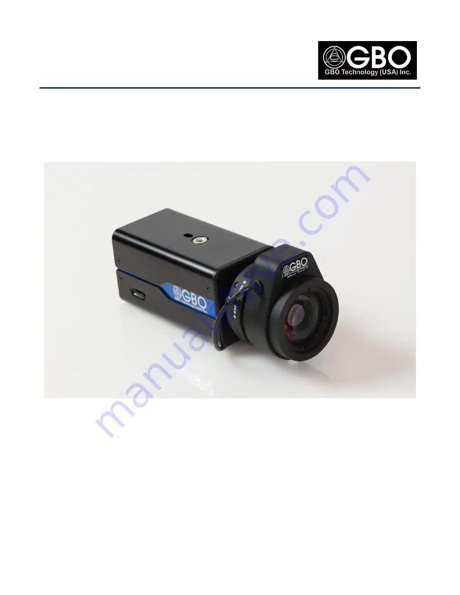
S1080 HD™ NETWORK CAMERA


User’s Guide 


S1080 Series:  Ultra Low Light Camera


BETTER VIDEO ALL DAY/ALL NIGHT 


Unpublished copyright @2013 GBOT Technology, Inc.  All rights reserved.  This document is the property of and contains information 
proprietary to GBOT Technology, Inc.  No part of this document may be reproduced, transmitted, transcribed, stored in a retrieval system, or 
translated into any language or computer language, in any form or by any means, electronic, mechanical, magnetic, optical, chemical, manual 

or otherwise, without the written permission of GBOT Technology, Inc


Summary of Contents for S1080 Series

Page 1: ...ent is the property of and contains information proprietary to GBOT Technology Inc No part of this document may be reproduced transmitted transcribed stored in a retrieval system or translated into an...

Page 2: ...u do not agree to the terms of this agreement promptly return the software and the equipment unopened and unused including written materials and containers to the location where you obtained them for...

Page 3: ...Set Static IP Address via Web Browser GUI Camera Side 25 6 0 WEB BROWSER GUI SCREEN 27 6 1 Live Video Streaming Screen 27 6 1 1 Select Stream Drop Down List 27 6 1 2 Display all Streams Checkbox 28 6...

Page 4: ...10 2 1 Zone Selection Region of Privacy 48 10 3 Face Detect Setting 49 10 4 Region of Interest 49 10 4 1 Confidence Level 49 10 4 2 Direction 50 10 5 Privacy Mask Setting 50 11 0 CAMERA SETTINGS 51 1...

Page 5: ...r SNTP Server Data at the Network and Port Screen 64 15 5 Time in Camera 64 15 5 1 Date and Time 64 16 0 NETWORK AND PORT SETTINGS 65 16 1 Keep Network Settings While Reset Parameters to Default Check...

Page 6: ...19 2 Unmount Mount Button 77 19 3 Filelist of Memory Card Table 77 19 4 No SD Card Installed 78 20 0 MAINTENANCE PAGE 79 20 1 Event Logs 79 20 1 1 System Logs 79 20 1 2 Access Logs 81 20 2 Camera Stat...

Page 7: ...en 3 14 Figure 2 24 GBOT IP Network Camera Log In Screen 2 14 Figure 2 25 Web Browser GUI Screen Live Video Screen 2 15 Figure 3 1 Internet Explorer Screen Tools Manage add ons 16 Figure 3 2 Manage Ad...

Page 8: ...Figure 10 8 Live Video Screen Showing Privacy Zones 48 Figure 10 9 Region Of Interest Screen 49 Figure 11 1 Camera Settings Screen 51 Figure 12 1 Camera Advanced Screen 54 Figure 13 1 Camera Pan Tilt...

Page 9: ...ace Detect Options 49 Table 10 2 Face Detection Directions 50 Table 11 1 White Balance Mode Options 52 Table 12 1 Maximum Shutter Speed Options 55 Table 12 2 Minimum Shutter Speed Options 55 Table 12...

Page 10: ...Manual Page viii of viii Company Proprietary August 22 2013 Touch Screen Users The instructions in this manual are written for regular personal computers For touch screen computers simply substitute...

Page 11: ...a DC Iris lens is being used a DIP switch setting on the back of the camera needs to be changed Figure 1 1 Example of a DC Iris Lens and its Cable At the back of the camera there are two DIP switches...

Page 12: ...the camera is rebooting This causes the camera to revert all of its settings including its IP address to factory default values This provides the cleanest boot sometimes called a stone age boot Table...

Page 13: ...e Manager From the internet download the OnVIF Device Manager application from http sourceforge net projects onvifdm After the application has down loaded the OnVIF icon displays on your desktop Figur...

Page 14: ...cable into a power outlet Figure 2 3 12V DC Power Supply Cable Inserted into Receptacle in Camera Back 4 Wait until the two camera LEDs light up Initially they are red in color then change to orange...

Page 15: ...Main Screen 6 At the OnVIF Main Screen check the Remember see Figure 2 6 7 Enter your Name and Password Name admin Password 9999 Figure 2 6 Log In Screen 8 Click on the Log in button 9 Your camera s...

Page 16: ...see Figure 2 5 click on Web page and a black screen opens with a message that asks you to allow add ons before the GBOT IP Network Camera Log In Screen can be opened see Figure 2 11 2 Click on the All...

Page 17: ...your Internet Explorer screen click on the Settings icon located in the upper right hand corner of the screen Figure 2 8 Internet Explorer Screen 2 Click on Internet options and the Internet Options S...

Page 18: ...OnVIF Main Screen click on Web Page again Figure 2 10 OnVIF Main Screen 2 2 Click on the Allow button see Figure 2 11 and the GBOT IP Network Camera Log In Screen opens with the same question at the b...

Page 19: ...9999 and then click on the Submit button Figure 2 12 GBOT IP Network Camera Log In Screen Figure 2 13 Completed Log In Screen 2 After successful login a live video from the camera starts streaming in...

Page 20: ...t off Follow the instructions in Step 10 Set Browser Size to set your Browser to the correct size Step 11 Set Browser Size 1 At the Internet Explorer screen click on the Settings icon located in the u...

Page 21: ...g on the network the PC will obtain an Auto IP address in the 169 254 0 0 class B subnet See Section 4 0 IP address Provisioning via DHCP for detailed information on required PC settings Step 3 Connec...

Page 22: ...switch to your PC see Figure 2 18 2 Using standard Ethernet cable s connect the POE switch to the camera s through the LAN POE receptacle s located on the back of the camera s see Figure 2 19 Figure...

Page 23: ...to the PC s Network dialog box Under Other Devices double click the GBOT_DD EE FF icon where DD EE FF represents the last three bytes of the camera s media access control MAC address Figure 2 20 UPnP...

Page 24: ...3 Permission Screen 3 Step 4 Log In via Web Browser GUI 1 The GBOT IP Network Camera Log In screen displays when the connection to the GBOT S1080 IP Network Camera has been successful Enter the User N...

Page 25: ...the camera starts streaming in the Live Video section of the Web Browser GUI Screen which has two sections 1 the Live Video Section and 2 the Navigation Panel At the top of the screen are control ico...

Page 26: ...hese steps need to be performed whenever the camera firmware is updated It is assumed that a previous version of the camera firmware has been uploaded 1 From Internet Explorer menu select Tools Manage...

Page 27: ...22 2013 Company Proprietary Page 17 of 87 Figure 3 2 Manage Add ons Screen 3 When the Manage Add ons Screen opens scroll to find GoDB Class right click on it and then select More Information from the...

Page 28: ...n the More Information Screen opens click on Remove all sites click on Remove and then click on Close Figure 3 4 More Information Screen 5 Back at the Manage Add ons Screen scroll down to find GFFMpeg...

Page 29: ...pany Proprietary Page 19 of 87 6 At the More Information Screen click on Remove all sites click on Remove and then click on Close Figure 3 6 More Information 2 7 Close Internet Explorer to complete th...

Page 30: ...llow the steps below 1 On your desktop right click on the Ethernet icon and the Network and Sharing Center dialog box opens see Figure 4 4 Go to step 3 Figure 4 1 Ethernet Icon 2 Or open your Control...

Page 31: ...k Connections Dialog Box 5 Scroll down and double click on Internet Protocol Version 4 TCP IPv4 and the Internet Protocol Version 4 TCP IPv4 Properties dialog box opens Figure 4 6 Ethernet Properties...

Page 32: ...the following IP address radio button Figure 5 1 Internet Protocol Version 4 TCP IPv4 Properties Dialog Box 2 3 Obtain information from your local IT personnel to complete the IP address Subnet mask a...

Page 33: ...ini A Cable Receptacle on Camera Back Panel 2 Connect the universal serial bus USB end of the cable to the PC 3 Allow a short time for the PC to detect the new USB storage device from the GBOT S1080 I...

Page 34: ...6 Detailed Network Settings 6 Enter the desired network configuration information including the IP address 7 Click the Exit E button to quit the USBconf Utility and disconnect the USB cable 8 The sett...

Page 35: ...thods a Documentation from prior configuration b Factory default Refer to Section 1 2 Reset Factory Default Values for details of how to reset the camera c USBconf utility Refer to Section 5 2 View IP...

Page 36: ...oximately 60 seconds When the LAN LED changes color from red to orange and then to green the network connection is ready Figure 5 9 Network Settings Change Confirmation 6 Close Internet Explorer and f...

Page 37: ...d in the sections below Figure 6 1 Web Browser GUI Screen Live Video Screen 6 1 LIVE VIDEO STREAMING SCREEN At the top of the Live Video Streaming Screen are the icons drop down lists checkbox and Log...

Page 38: ...ideo Screen opens select Single Dual or Tri Stream from the StreamType drop down list see Figure 6 5 Figure 6 5 Settings Video StreamType 6 1 3 1 SAVE CHANGES Click the Ok button at the Video Screen t...

Page 39: ...ee Figure 6 10 Figure 6 8 Live Video All Streams Screen 6 1 4 Icons These icons allow the user to expand the size of the streaming video screen make a snapshot of the live video stream set recording c...

Page 40: ...nded Live Video Streaming Screen Figure 6 12 Close 1X Mode Button 6 1 4 2 SNAPSHOT ICON 1 Click on the Snapshot icon to capture and store the first resolution JPEG image of whatever the camera is seei...

Page 41: ...tive to activate The alarm icon changes color from white to orange to give the user a visual signal that the alarm state has changed Figure 6 16 Alarm Status Icon Alarm Inactivated and Alarm Activated...

Page 42: ...isual signal that the audio state has changed Figure 6 18 Audio Icon Toggle OFF to ON 6 1 4 6 SD CARD EXPLORER ICON This icon is only available if an SD card has been previously inserted into the SD r...

Page 43: ...e Drop down List 6 1 5 Logout Button Click on the Logout button to close the Web Browser GUI Live Video Screen 6 2 NAVIGATION PANEL The Navigation Panel for the S1080 IP Network Camera is located on t...

Page 44: ...e your password as soon as possible since the default password is the same for For example you may want to add Admin 1 Admin 2 etc 1 At the Web Browser GUI Screen see Figure 6 1 click on Add Edit User...

Page 45: ...cannot use any function or set any parameters The user information displayed in the Add Edit Users Screen may be edited or deleted After entering any new information click the Ok button for the chang...

Page 46: ...ccess Control Settings Feature Authority Admin Operator Viewer Live Video Main Screen Yes Yes Yes Video Image Settings Yes Yes No Advanced Features Settings Yes Yes No Camera Settings Yes Yes No Audio...

Page 47: ...the Stream Type to Single and the H 264 profile to Base Base is the least CPU intensive setting while High is the most CPU intensive setting The bit rate is the rate at which bits are transferred fro...

Page 48: ...resolution Triple This enables the triple stream use cases 8 2 3 Codec Combo Refer to APPENDIX A Definitions for more information on codecs Select the desired Codec from the drop down list described i...

Page 49: ...ollowing required options from the drop down list described in the table below Table 8 5 Mirror Options Mirror Options OFF Turns OFF option VERTICAL Flips the data in the vertical direction HORIZONTAL...

Page 50: ...per second 8 4 2 Bit Rate Enter the required bit rate for both the MPEG4 Setting and the H 264 Setting Bit rate values range from 64 to 12000 for Stream 1 and 64 to 8000 for Stream 2 Stream 3 8 4 3 R...

Page 51: ...ed image Select from the drop down list Top Left or Top Right 8 5 4 Text Click on Enable Text checkbox to activate the text function This enables disables insertion of a pre selected text onto a speci...

Page 52: ...ens see Figure 9 1 The fields drop down lists and radio buttons on this screen are described in the sections below NOTES 1 To use Advanced Options the user needs to know the Codec interfaces and impli...

Page 53: ...Macro Blocks When Rate Control is in OFF position this value is used to encode all the frames Min Minimum Value of QP with which Codec encodes the Macro Blocks Max Maximum Value of QP with which Codec...

Page 54: ...anced Video and Region of Interest Screens 3 Drag the mouse to draw the Region Clicking on the Delete button removes the region 4 Optionally the user can enter the value directly into the X Y W and H...

Page 55: ...the Advanced Features screen opens see Figure 10 1 The fields drop down lists and radio buttons on this screen are described in the sections below Figure 10 1 Advanced Features Screen 10 1 MOTION DET...

Page 56: ...horizontal and 6 vertical Place the mouse cursor on the video frame and left click on the desired section and the striped red zone rectangles display The user can set more than one targeted zone Click...

Page 57: ...0 5 Setting Saved to Camera Message 3 At the Live Video Screen the selected area blinks to alert the user to motion in that area and the alarm icon turns orange Figure 10 6 Motion Detected Visual Noti...

Page 58: ...he Motion Detection Setting Screen see Figure 10 3 1 Click the Enable Region of Privacy checkbox to activate the privacy blocking feature 2 Place the mouse cursor on the video frame and left click on...

Page 59: ...frames 10 4 REGION OF INTEREST Clicking on the Configure button enables the region of interest based face detection mask feature Faces are detected or masked only in the region specified by the user...

Page 60: ...Table 10 2 Face Detection Directions Direction Options UP detects faces in upward direction default LEFT detects faces in left direction RIGHT detects faces in right direction 10 5 PRIVACY MASK SETTI...

Page 61: ...G CONDITIONS 11 1 1 Brightness Use the slider to specify the desired brightness level from 1 to 255 or enter a value in the field A higher value of the brightness gives a brighter scene 11 1 2 Contras...

Page 62: ...and affects the display in PAL mode 11 1 7 White Balance Specify one of the following white balance modes from the drop down list as described in the table below The default value is Auto Normal Refe...

Page 63: ...tary Page 53 of 87 11 2 LENS DISTORTION CORRECTION Enable disable lens distortion ON or OFF NOTE Video Stabilization and Lens Distortion Correction are not supported for resolutions above 720P Click o...

Page 64: ...o specify the desired noise filter level from 1 to 255 A higher value provides higher strength of the noise filter 12 2 EV Use the slider to specify the desired exposure compensation level from 1 to 2...

Page 65: ...50 1 2000 1 4 1 30 default 1 250 1 1000 1 10000 1 8 1 60 1 500 1 1500 1 100000 Table 12 2 Minimum Shutter Speed Options Minimum Shutter Speed Options 1 30 default 1 120 1 500 1 1000 1 2 000 1 100000 1...

Page 66: ...ter Time for Manual Mode Manual Mode Options seconds 1 2 1 15 1 120 1 750 1 2000 1 4 1 30 1 250 1 1000 1 10000 1 8 1 60 1 500 1 1500 1 100000 12 7 1 Gain Select the gain from the drop down list descri...

Page 67: ...down lists and radio buttons on this screen are described in the sections below Figure 13 1 Camera Pan Tilt Screen 13 1 PAN SPEED Use the slider to specify the desired pan speed from 0 to 64 the defau...

Page 68: ...t for the changes to take effect 13 6 CENTER Click first on the Center button and then click on the Store button to center the camera on the desired location Or use the directional arrows to move the...

Page 69: ...ibed in the sections below Figure 14 1 Audio Setting Screen 14 1 ENABLE AUDIO Click the Enable Audio checkbox to enable disable audio functionality in the camera Figure 14 2 Enable Audio Checkbox 14 2...

Page 70: ...Rate Specify audio capture sampling rate from the drop down list Both 8Khz and 16Khz are supported 14 3 4 Bit Rate The bitrate is in Auto mode 64kbps 14 3 5 Alarm Level Use the slider to specify the...

Page 71: ...ion B August 22 2013 Company Proprietary Page 61 of 87 14 4 AUDIO OUTPUT 14 4 1 Output Volume Using the slider specify the audio playback volume from 1 100 Click on the Ok button to save any changes a...

Page 72: ...ow Figure 15 1 Date Time Screen 15 1 SET TIME ZONE AND FORMATS Before you make any selections select your Time Zone from the drop down list There are 25 time zones for the user to select If this is no...

Page 73: ...ox so that the camera software can automatically adjust when the time changes twice a year NOTE Daylight Savings Time is implemented for several of the zones given in the drop down list but not all 6...

Page 74: ...ick on the Automatically Adjust for Daylight Saving Time checkbox so that the camera software can automatically adjust when the time changes twice a year 4 Click on the Ok button to save the changes a...

Page 75: ...n 16 1 KEEP NETWORK SETTINGS WHILE RESET PARAMETERS TO DEFAULT CHECKBOX When using the Maintenance screen see Figure 20 1 to RESET all camera settings to the factory default values click on the Keep N...

Page 76: ...erver IP address Each value can be from 0 to 255 The DNS Server translates the domain name to an IP address 16 3 FTP TAB NOTE 1 Before setting all the parameters first build the FTP server For more in...

Page 77: ...red account name Password Enter the password Sender Enter valid e mail address of the sender SMTP Server Enter the required SMTP server domain name Email Address Enter the required e mail address of t...

Page 78: ...HTTP Port for the Web Server running inside the camera The default value is 80 Output ALARM OUT This is an alarm output trigger Connect it to external devices such as buzzers or lights It can be progr...

Page 79: ...d in the sections below Figure 17 1 Alarm Setting Screen 17 1 ENABLE ALARM CHECKBOX Click on the Enable Alarm checkbox to enable disable the alarm function of the camera 17 2 ALARM DURATION Select the...

Page 80: ...etection is triggered on a darker scene 17 3 4 2 RESET TAMPER When Tamper Detection is enabled checked this button is visible It resets the reference focus value based on the current scene If the curr...

Page 81: ...2 Audio Mode 5 For H 264 and MPEG4 files the number of files attached for SMTP is one even though it is set for higher values For the number of attachments a number higher than one is valid only for...

Page 82: ...io checkbox in order to play audio via the Audio Line Out on the back of camera Insert one end of the cable into the A V slot and the other end into the desired audio device Figure 17 2 Back of Camera...

Page 83: ...n the sections below Figure 18 1 Storage Screen 18 1 SAVE INTO LOCAL STORAGE Enable the Save into Local Storage checkbox to save the recording to the SD card in the camera only if an SD card is curren...

Page 84: ...om left hand side of the Storage screen Figure 18 2 Add and Remove Schedule Buttons 2 Click on this button to open or add a recording schedule and the Schedule screen opens Figure 18 3 Setting a Recor...

Page 85: ...for Recording 18 6 REMOVE ALL SCHEDULES The Remove All Schedules button is located at the bottom right hand side of the Storage screen see Figure 18 2 Click on this button to clear the fields in the...

Page 86: ...eb Browser GUI Screen see Figure 2 14 click on the SD Card Explorer icon and the SD Card Explorer screen displays The fields drop down lists and radio buttons on this screen are described in the secti...

Page 87: ...ure 19 3 SD Card and SD Card Inserted into Camera Receptacle The SD card can be inserted directly into your PC via a compatible card reader and the files can be viewed or deleted 19 3 FILELIST OF MEMO...

Page 88: ...ary August 22 2013 19 4 NO SD CARD INSTALLED If no SD card has been installed in the camera the SD card icon will not show in the icon list Figure 19 4 Icon List on Live Video Screen And you will not...

Page 89: ...ections below Figure 20 1 Maintenance Screen NOTE Some of the operations on this screen ask the user to re authenticate with username and password 20 1 EVENT LOGS There are two types of Event logs Sys...

Page 90: ...the Save button and the log html screen opens Click on Save Target As Enter the file name and click on the Save button Figure 20 3 Log html and Save as Screens 20 1 1 3 CLEAR Click on the Clear butto...

Page 91: ...the camera including date time and events Click on the Back button to return to the Maintenance screen Figure 20 5 Event Access Log 20 1 2 2 SAVE Right click on the Save button and the Log html Screen...

Page 92: ...Back button to return to the Maintenance screen Figure 20 6 Event Connection List 20 2 1 2 SAVE Right click on the Save button and the Log html Screen opens see Figure 20 3 Click on Save Target As En...

Page 93: ...Save button 20 2 2 3 RESET CAUTION In order to keep the IP address settings when the RESET option is used ensure that the Keep Network Settings while reset parameters to default checkbox is checked en...

Page 94: ...oot file system for upgrade the file name must start with ipnc_ otherwise this process will fail 2 During the upgrade process ensure that there are no user interactions with the camera Web Browser GUI...

Page 95: ...11 Upgrading Firmware Notification 20 6 WATCHDOG TIMER The camera automatically recovers if the system hangs up for the user specified length of time 10 seconds is the default Enter the time in secon...

Page 96: ...information is shown in the table below Table 21 1 Release Version Information Release Version Information Kernal Version specifies the version of the Linux Kernel running in the camera UBoot Version...

Page 97: ...ary Page 87 of 87 21 3 SUPPORT INFO User can scroll through this section for all Support related information 21 4 CREDITS User can scroll through this section for the Credits related information 21 5...

Page 98: ......

Page 99: ...odec is short for coder decoder which is what a codec does Most audio and video formats use some sort of compression so that they don t take up a huge amount of disk space Audio and video files are co...

Page 100: ...n profile supports the majority of encoding techniques so it need more code more memory and more processing power on the decoder side The High profile supports virtually all the H264 s encoding techni...

Page 101: ...n which each video frame or interlaced field of a digital video sequence is separately compressed as a JPEG image Originally developed for multimedia PC applications M JPEG is now used by video captur...

Page 102: ...ation OSD On screen Display PAL Phase Alternating Link In PAL countries use a multiple of 50 in NTSC countries use a multiple of 60 also see NTSC PC Personal Computer POE 802 3af Power over Ethernet s...

Page 103: ...a s shutter is open Shutter speed is a parameter that controls how long light is hitting the sensor It is usually measured in parts of a second 30 means 1 30s that is a thirtieth of a second Shutter t...

Reviews: