GSP665x-EVBIMS2
High Power IMS 2 Evaluation Platform
Technical Manual
_____________________________________________________________________________________________________________________
GSP665x-EVBIMS2 TM rev. 201021
© 2020 GaN Systems Inc.
Please refer to the Evaluation Board/Kit Important Notice on page 22
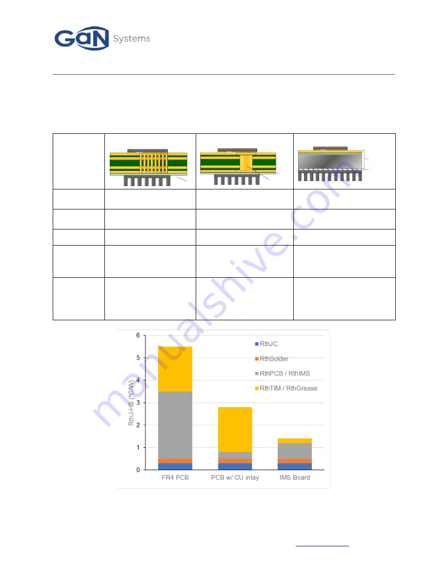
Table 3 compares 3 different design approaches for cooling discrete SMT power devices. While the cost is
lower for a FR4 PCB cooling with thermal vias, the IMS board offers the best performance for thermal
management. Figure 4 provides a quantitative comparison of the thermal resistance for the 3 design
options. The IMS board clearly comes out ahead.
Table 3 Performance comparison of 3 thermal design options for SMT power devices
IMS PCB
The rm al
gre ase
IMS
Boa rd
Thermal
resistance
Good
Better
Best
Electrical
Insulation
No, additional TIM
needed
No, additional TIM needed
Yes
Cost
Lowest
High
Low
Advantages
•
Standard process
•
Lowest cost
•
Layout flexibility
•
Layout flexibility
•
Improved thermal
compared to thermal vias
•
Lowest thermal resistance
•
Electrically isolated
Design
challenges
•
High PCB thermal
resistance
•
Cu-inlay surface
coplanarity
•
High TIM thermal
resistance
•
Layout limited to 1 layer
•
Parasitic inductance
•
Coupling capacitances to
the metal substrate
Figure 4 Comparison of Junction to Heatsink thermal resistance (R
thJ-HS
) (Estimated based on GS66516B)
FR4 PCB Cooling with Vias
TIM
FR4 PCB with Cu inlay
Cu-inlay
TIM


