Page 42
GP2X User Guide –
www.emuholic.com
1 - Ensure that the GP2X and breakout board are switched off
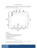
2 - Connect the EXT cable to the GP2X and breakout board ports.
TV-Out
1 - Connect the S-Video cable to the breakout board and your television
2 - Connect the Left and Right (White and Red) RCA Jacks to the breakout board and your television.
3 - Connect the DC 3V adaptors to the GP2X and breakout board if you have a MK1 GP2X.
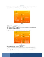
4 - Switch on the GP2X and once at the menu, go to the TV-Out screen and enable TV-Out. Further information
can be found on page 27.
USB
1 - Connect your USB device(s) such as a joystick, mouse or keyboard to the breakout board.
2 - Connect the DC 3V adaptors to the GP2X and breakout board if you have a MK1 GP2X.
3 - Switch on the GP2X and once at the menu, go to the System screen.
4 - Please refer to page 30 for information on enabling USB devices.
5 - Exit the System screen and after a few seconds the USB Lamps should switch on for each USB device
connected.
NOTE: Not all software supports USB devices such as joysticks, mouse and keyboard. Please refer to the
software documentation for further information.
RS232
1 - Connect the 9 pin serial cable to the breakout board and your PC serial port.
2 - Connect the DC 3V adaptors to the GP2X and breakout board if you have a MK1 GP2X.
3 - Please refer to page 39 for example of using the serial debug cable.
JTAG
1 - Connect the 25 pin parallel cable to the breakout board and your PC parallel port.
2 - Connect the DC 3V adaptors to the GP2X and breakout board if you have a MK1 GP2X.
I will add further information on JTAG usage in the next guide update.


