


Page 8
3E4237 Gallagher T15 Reader | Edition 11 | February 2022
Copyright © Gallagher Group Limited
4 Installation
ATTENTION:
This equipment contains components that can be damaged by
electrostatic discharge. Ensure both you and the equipment are earthed before
beginning any servicing.
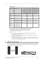
The Gallagher T15 Reader is designed to be mounted on any solid flat surface. However installation on
metal surfaces, particularly those with a large surface area will reduce read range. The extent to which
the range is reduced will depend upon the type of metal surface.
Note:
Consideration should be given to the installation environment when using Bluetooth® enabled
readers, as the read range may be reduced.
The recommended mounting height for the reader is 1.1 m (3.6 ft) from the floor level to the centre of
the reader device. However this may vary in some countries and you should check local regulations for
variations to this height.
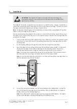
1.
Use the reader bezel as a guide to drill all three holes. Drill the 13 mm (1/2 inch) diameter centre
hole (this is the centre hole for which the building cable will exit the mounting surface) and the
two fixing holes.
2.
Run the building cabling out through the centre hole and through the reader bezel.
3.
Secure the bezel to the mounting surface using the two fixing screws provided. It is important
the bezel of the reader is flush with and tight against the mounting surface. Three screw
locations have been provided. Gallagher recommend using the outer screw locations.
Note:
It is strongly recommended that you use the screws provided. If an alternative screw is
used, the head must be no larger nor deeper than that of the screw provided.
Note:
Ensure the centre hole allows the cable to run freely out through the mounting surface, so
that the reader facia can clip into the bezel.
Bezel
Building cable
No. 6 pan head screw
No. 6 pan head screw
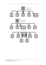
4.
Connect the reader tail extending from the facia assembly to the building cable. Connect the
wires for the appropriate reader you wish to interface, either an HBUS Reader or a Cardax IV
Reader, as shown in the following diagrams.
Note:
PIV and Bluetooth® enabled readers must be connected as HBUS Readers. PIV readers
connect to the Gallagher Controller 6000 High Spec PIV (C305101) only.