Galil DMC-41x3 Скачать руководство пользователя страница 14

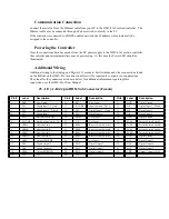
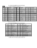
J8 - I/O (E-H) 44 pin HD D-Sub Connector (Female)

4183


For DMC-4153 thru DMC-4183 controllers only. 

Pin#

Label

Description

Pin#

Label

Description

Pin#

Label

Description

1

ERR

Error Output

16

RST*

Reset Input

31

GND

Digital Ground

2

DI9

Digital Input 9 / E latch

17

INCOM1

Input Common (DI 9-16)

32

DI10

Digital Input 10 / F latch

3

DI12

Digital Input 12/H latch

18

DI11

Digital Input 11 / G latch

33

DI13

Digital Input 13

4

DI15

Digital Input 15

19

DI14

Digital Input 14

34

DI16

Digital Input 16

5

ELO*

Electronic Lock Out

20

ABRT*

Abort Input

35

GND

Digital Ground

6

LSCOM1

Limit Switch Com (E-H)

21

N/C

No Connect

36

FLSE

Forward Limit Switch E

7

HOME

Home Switch E

22

RLSE

Reverse Limit Switch E

37

FLSF

Forward Limit Switch F

8

HOMF

Home Switch F

23

RLSF

Reverse Limit Switch F

38

FLSG

Forward Limit Switch G

9

HOMG

Home Switch G

24

RLSG

Reverse Limit Switch G

39

FLSH

Forward Limit Switch H

10

HOMH

Home Switch H

25

RLSH

Reverse Limit Switch H

40

GND

Digital Ground

11

OP1A

Output GND/PWR

26

N/C

No Connect

41

DO9

Digital Output 9

12

DO11

Digital Output 11

27

DO10

Digital Output 10

42

DO12

Digital Output 12

13

DO14

Digital Output 14

28

DO13

Digital Output 13

43

DO15

Digital Output 15

14

OP1B

Output PWR/GND

29

DO16

Digital Output 16

44

CMP

Output Compare (E-H)

15

+5V

+5V

30

+5V

+5V


* ABRT, RST and ELO use INCOM0

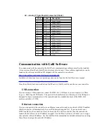
Jn1 - Encoder 26 pin HD D-Sub Connector (Female)

Pin 
#

Label

Description

Pin #

Label

Description

1

HALC

Hall C

14

FLS

Forward Limit Switch Input

2

AEN

Amplifier Enable

15

AB+

B+ Aux Encoder Input

3

DIR

Direction 

16

MI-

I- Index Pulse Input

4

HOM

Home

17

MB+

B+ Main Encoder Input

5

LSCOMn

Limit Switch Common*

18

GND

Digital Ground

6

AA-

A- Aux Encoder Input

19

MCMD

Motor Command

7

MI+

I+ Index Pulse Input

20

ENBL+

Amp Enable Power

8

MA-

A- Main Encoder Input

21

HALA

Hall A

9

+5V

+5V 

22

RLS

Reverse Limit Switch Input

10

GND

Digital Ground

23

AB-

B- Aux Encoder Input

11

ENBL-

Amp Enable Return

24

AA+

A+ Aux Encoder Input

12

HALB

Hall B

25

MB-

B- Main Encoder Input

13

STP

PWM/Step 

26

MA+

A+ Main Encoder Input

LSCOMn on JA1, JB1, JC1 and JD1 is common to LSCOM0 on J5
LSCOMn on JE1, JF1, JG1 and JH1 is common to LSCOM1 on J8

Содержание DMC-41x3

Страница 1: ...ted Amplifier Installation Manual Manual Rev 1 0a3 By Galil Motion Control Inc Galil Motion Control Inc 270 Technology Way Rocklin California 95765 Phone 916 626 0101 Fax 916 626 0102 E mail Address support galilmc com URL www galilmc com Rev 02 29 12 ...

Страница 2: ...covers the basic installation of the controller and amplifier modules For full operational information including specific I O installation detailed programming examples and additional internal driver information see the DMC 41x3 User Manual WARNING Machinery in motion can be dangerous It is the responsibility of the user to design effective error handling and safety protection as part of the machi...

Страница 3: ...e stand alone unit The DMC 4113 4123 4133 4143 are one thru four axes controllers and the DMC 4153 4163 4173 4183 are five thru eight axes controllers All eight axes have the ability to use Galil s integrated amplifiers or drivers and connections for integrating external devices Commands are sent in ASCII Additional software is available for automatic tuning trajectory viewing on a PC screen and p...

Страница 4: ...20 contains 2 amplifiers Each amplifier drives motors operating at up to 8 Amps continuous 15 Amps peak 20 60 VDC The gain settings of the amplifier are user programmable at 0 4 Amp Volt 0 8 Amp Volt and 1 6 Amp Volt The switching frequency is 33 kHz The amplifier offers protection for over voltage under voltage over current short circuit and over temperature Two AMP 43540s or AMP 43520 s can be u...

Страница 5: ...nd the mounting hole locations are found in Appendices A3 and A4 Additional Mounting Consideration when using the AMP 43xx0 When operating a DMC 41x3 D3xx0 D3xx0 or a DMC 41x3 D3xx0 special mounting considerations must be made if the total continuous current output for the controller is greater than 15A for a 1 4 axis controller and greater than 30A for a 5 8 axis controller In this case the contr...

Страница 6: ...tive components Observe standard precautions for handling ESD sensitive devices when handling the controller 1 Verify that the following components have been shipped along the motion controller Connectors and mating pins for motor power and amplifier power o Qty 4 4 pin molex connectors for EACH internal amplifier o Qty 1 6 pin molex connector for EAH internal amplifier Galil Software Installation...

Страница 7: ...Figure 1 Label for DMC 41x3 Figure 2 Label for DMC 41x3 D3220 Figure 3 Label for DMC 41x3 D3240 Figure 4 Label for DMC 41x3 D3520 Figure 5 Label for DMC 41x3 D3540 ...

Страница 8: ...Figure 6 Label for DMC 41x3 D3240 D3220 Figure 7 Label for DMC 41x3 D3240 D3240 Figure 8 Label for DMC 41x3 D3540 D3520 Figure 9 Label for DMC 41x3 D3540 D3540 Figure 10 Label for DMC 41x3 D3240 D3520 ...

Страница 9: ...Figure 11 Label for DMC 41x3 D3240 D3540 Figure 12 Label for DMC 41x3 D3540 D3220 Figure 13 Label for DMC 41x3 D3540 D3240 Figure 14 ETL Mark ...

Страница 10: ...sed it should be determined at this time whether or not an additional heat sink will be required This is determined based upon the continuous current requirements of the system as defined in the Additional Mounting Consideration when using the AMP 43xx0 section above The Motor Sizer tool found on our website can be used to determine this value http www galilmc com learning motorsizer php Figure 15...

Страница 11: ...llation of the controller Marked as the disconnect device for the equipment Connectors for AMP 43xx0 On Board Connector Terminal Pins POWER 6 pin MATE N LOK MOLEX 39 31 0060 MOLEX 44476 3112 A B C D 4 pin Motor Power Connectors 4 pin MATE N LOK MOLEX 39 31 0040 MOLEX 44476 3112 For mating connectors see http www molex com Power Connector Pin Number Connection 1 2 3 DC Power Supply Ground 4 5 6 VS ...

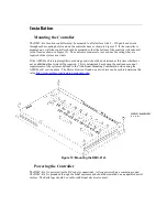
Страница 12: ...Figure 16 DMC 41x3 wiring with AMP 43xx0 ...

Страница 13: ...n Label Description Pin Label Description Pin Label Description 1 ERR Error Output 16 RST Reset Input 31 GND Digital Ground 2 DI1 Digital Input 1 A latch 17 INCOM0 Input Common DI 1 8 32 DI2 Digital Input 2 B latch 3 DI4 Digital Input 4 D latch 18 DI3 Digital Input 3 C latch 33 DI5 Digital Input 5 4 DI7 Digital Input 7 19 DI6 Digital Input 6 34 DI8 Digital Input 8 5 ELO Electronic Lock Out 20 ABRT...

Страница 14: ...Ground 11 OP1A Output GND PWR 26 N C No Connect 41 DO9 Digital Output 9 12 DO11 Digital Output 11 27 DO10 Digital Output 10 42 DO12 Digital Output 12 13 DO14 Digital Output 14 28 DO13 Digital Output 13 43 DO15 Digital Output 15 14 OP1B Output PWR GND 29 DO16 Digital Output 16 44 CMP Output Compare E H 15 5V 5V 30 5V 5V ABRT RST and ELO use INCOM0 Jn1 Encoder 26 pin HD D Sub Connector Female Pin La...

Страница 15: ...ort manuals galiltools introduction html Once the software has been installed run GalilTools or GalilTools Lite and choose your controller USB connection If you are using a USB connection connect the DMC 41x3 USB port to your computer via a Male Type A Male Type B USB cable The port will be identified as a new Serial port The USB port is designed for basic communication to the controller and the s...

Страница 16: ...its Specification Maximum Input Voltage VDC 60 Minimum Input Voltage VDC 20 Maximum Input Power W 1920 Maximum Output Current Amps 64 AMP 43240 Description Units Specification Supply Voltage VDC 20 60 Maximum Input Power W 1200 Continuous Output Current per axis Amps 10 Peak Output Current per axis Amps 20 Amplifier Gain A V 0 5 1 0 default 2 0 Switching Frequency kHz 24 Brushless Motor Commutatio...

Страница 17: ...ion angle 120 Supply Voltage Fuse Amps 30 Fault Information The AMP 43240 and AMP 43540 are protected from the following fault conditions Fault Condition AMP 43540 AMP 43240 Over Current Protection yes yes Under Voltage Protection yes yes Over Temperature Protection yes yes Over Voltage Protection yes yes Hall Error Detection yes yes The Over Current protection circuit is shown in Figure 17 For fu...

Страница 18: ...Overcurrent Circuit A2 Environmental Specifications Description Units Specification Storage Temperature C 40 to 125 Operating Temperature C 0 to 40 Operating Altitude feet 10 000 Humidity RH 20 95 non condensing ...

Страница 19: ...0 D3240 Length in 11 50 Width in 7 25 Height in 1 50 DMC 4183 D3240 D3240 Included Components Quantiy Description DMC 4183 1 Main Controller Board AMP 43240 2 Servo Amplifier Board DMC 4183 D3540 D3540 Included Components Quantiy Description DMC 4183 1 Main Controller Board AMP 43540 2 Servo Amplifier Board ...

Страница 20: ......

Страница 21: ...A4 Mechanical Specifications DMC 4143 Description Units Specification Weight lb 2 7 DMC 4143 D3240 Length in 8 05 Width in 7 25 Height in 1 50 ...

Отзывы: