


1
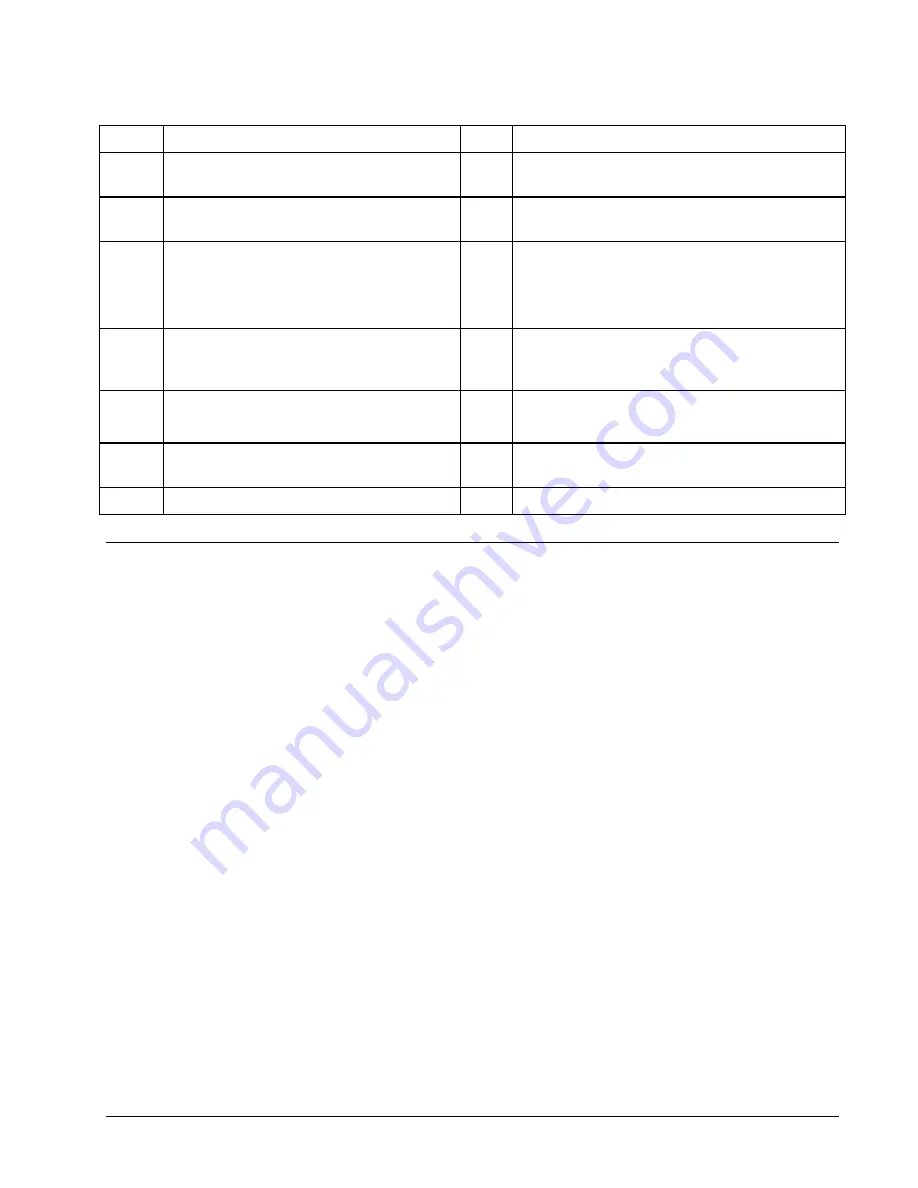
DMC-141X Flash EEPROM
J2
10Base-T Ethernet connection
2
Motorola 68331 microprocessor
J3
37 Pin-D connection for controller signal break-
out
3
GL-1800 custom gate array
J4
15 Pin-D connection for controller main encoder
breakout (DMC-1416)
4
Reset switch
J5
6 Pin power connector for +5V, +12V and –12V
input (DMC-1415/DMC-1425)
5 Pin connector for 20 – 60V DC supply and
motor connections (DMC-1416)
5
Error LED’s for active Ethernet
connection, transmit/receive on Ethernet,
error output and power.
JP1
Master reset , upgrade and baud rate selection
jumpers, Y step
6
Controller RAM
JP2
Motor off as default jumper.
Stepper motor jumper (DMC-1415/DMC-1425)
7
Fuse for DC-to-DC converter.
JP3
Jumper for selecting analog motor command or
step and direction pin-out configuration.
J1
RS232 Serial connection
Elements You Need
Before you start, you must get all the necessary system elements. These include:
1.
DMC-1415, DMC-1425 or DMC-1416 Controller, and 37-pin cable (order Cable -37).
2. Servo motor(s) with Encoder or stepper motor.
3. Appropriate motor drive - servo amp (Power Amplifier or AMP-1460) or stepper drive.
4.
Power Supply for Amplifier
5.
+5V,
±
12V supply for DMC-1415 or DMC-1425 card level
6.
20V to 60V DC supply for DMC-1416
7.
Communication CD from Galil
8.
WSDK Servo Design Software (not necessary, but strongly recommended)
9.
Interface Module ICM-1460 with screw-type terminals or integrated Interface
Module/Amplifier, AMP-1460. (Note: An interconnect module is not necessary, but strongly
recommended.)
The motors may be servo (brush or brushless type) or steppers. The driver (amplifier) should be
suitable for the motor and may be linear or pulse-width-modulated and it may have current feedback or
voltage feedback.
For servo motors, the drivers should accept an analog signal in the +/-10 Volt range as a command.
The amplifier gain should be set so that a +10V command will generate the maximum required current.
For example, if the motor peak current is 10A, the amplifier gain should be 1 A/V. For velocity mode
amplifiers, a command signal of 10 Volts should run the motor at the maximum required speed.
For step motors, the driver should accept step and direction signals. For start-up of a step motor
system refer to Step 8c “Connecting Step Motors”.
8
i
Chapter 2 Getting Started
DMC-14x5/6
Artisan Technology Group - Quality Instrumentation ... Guaranteed | (888) 88-SOURCE | www.artisantg.com


