9
2
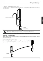
24V DC
2
1
1
2
English
Preparation
Taking into use
The following actions must be carried out in the sequence stated for each motor-unit. (Both
motor-units of a tandem system* must be connected when going through items CH3).
1 - Preparing motor-unit (p. 11).
2 – Programming the curtain end-positions (CH3).
3 – Before coupling the motor-units (BUS): adjusting the end-motors (CH5).
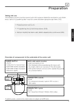
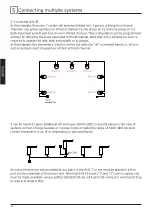
Overview of components in the underside of the motor-unit
*) tandem system: consists of two motor-units on a single rail (6200 only).
POWER SUPPLY
- 24V DC
- Connection for transformers
6230-1000 (6200) (standard)
6330-1000 (6300) (standard)
DIN power supply
Button
Open
Button
Close
LED’s with switch function
- Light up in green or red
- Give feedback while programming the motor-unit:
See chapter B6 for an overview of the LED signals.
- LED switch function: can be used to operate the system
as a 2-button switch.
CONNECTOR 2 (black)
- RJ45
- For connection infrared / switch / RF-receiver /
BUS cables
CONNECTOR 1 (grey)
- RJ45
- For connection infrared / RS232 / BUS cables
Содержание 6200 Series
Страница 2: ...Wijzigingen voorbehouden Changes reserved nderungen R serve de changement...
Страница 12: ...8 Nederlands...
Страница 16: ...12 Nederlands...
Страница 20: ...16 Nederlands...
Страница 22: ...18 Nederlands...
Страница 36: ......
Страница 46: ...8 English...
Страница 50: ...12 English...
Страница 54: ...16 English...
Страница 56: ...18 English...
Страница 70: ......
Страница 80: ...8 Deutsch...
Страница 84: ...12 Deutsch...
Страница 88: ...16 Deutsch...
Страница 90: ...18 Deutsch...
Страница 104: ......
Страница 106: ...Wijzigingen voorbehouden Changes reserved nderungen R serve de changement...
Страница 116: ...8 Fran ais...
Страница 120: ...12 Fran ais...
Страница 124: ...16 Fran ais...
Страница 126: ...18 Fran ais...
Страница 140: ...6200 GH00 Printed in the Netherlands 11 2010 Goelst Nederland B V www goelst com English Nederlands Deutsch Fran ais...

