background image

00066130.DOC, Version 1.0

22/28

Master/Slave operation

The master/slave operation enables that several devices can be synchronized and controlled by one master
device.

On the rear panel of the device you can find a DMX input plug and a DMX output connector, which can be
used for interconnecting several devices.

Choose the device which is to control the effects. Set the desired Master-mode on the master-device. This
device then works as master-device and controls all other slave-devices, which are to be connected to the
master-device via a balanced microphone lead. Connect the DMX out connectors with the DMX input plug of
the next device.

Set the desired mode for the master-device (see chapter Control Board). Set the DMX address 001 for all
slave-devices.

Connection with the mains

Connect the device to the mains with the enclosed power supply cable.

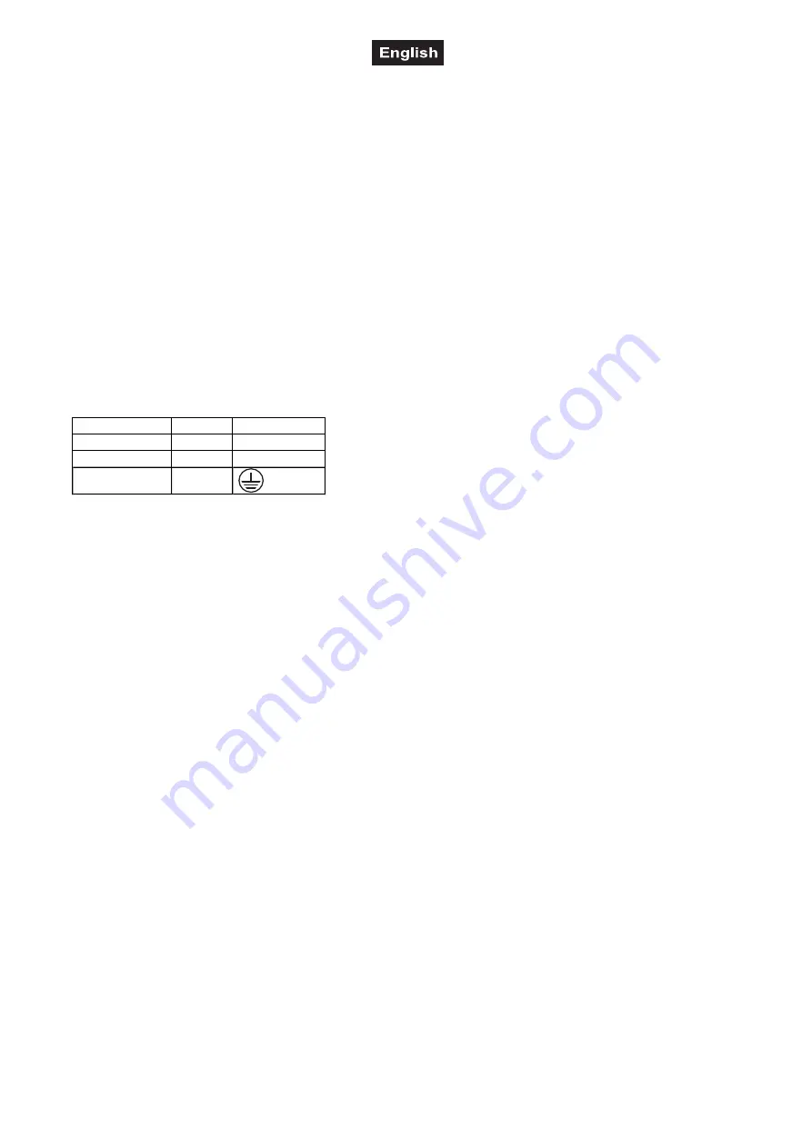
The occupation of the connection-cables is as follows:

Cable

Pin

International

Brown

Live

L

Blue

Neutral

N

Yellow/Green

Earth

The earth has to be connected!

If the device will be directly connected with the local power supply network, a disconnection switch with a
minimum opening of 3 mm at every pole has to be included in the permanent electrical installation.

The device must only be connected with an electric installation carried out in compliance with the IEC-
standards. The electric installation must be equipped with a Residual Current Device (RCD) with a maximum
fault current of 30 mA.

Lighting effects must not be connected to dimming-packs.

Please note: 

A maximum of 8 devices may be linked together. After every 8 devices, the fixtures must have

a renewed connection with the power mains.

Please make sure that open contacts are closed with the enclosed caps in order to avoid humidity
and dirt in the device.

OPERATION

After you connected the spot to the mains, the FUTURELIGHT WL-18 IP65 starts running.

The LED display lights up and you can choose the desired mode via the buttons MODE, ENTER, UP and
DOWN.

To prevent manipulation of the fixture, it is possible to activate the lock mode. The lock affects all menu
items.
1.  Call menu item PASS with the MODE button. Press the ENTER button. Use the button UP or DOWN to

select OFF (lock mode deactivated) or ON (lock mode active). Press the ENTER button confirm your
setting.

2.  To deactivate the lock mode a preset combination of buttons must be entered. For this press the buttons

in the following order: UP 

S

DOWN 

S

UP 

S

DOWN 

S

ENTER. For a correction of your input press the

ENTER button until all display segments are deleted and try again with the preset combination of
buttons.

Содержание WL-18

Страница 1: ...Copyright Nachdruck verboten Reproduction prohibited F r weiteren Gebrauch aufbewahren Keep this manual for future needs BEDIENUNGSANLEITUNG USER MANUAL WL 18 IP65 LED Architectural Spot...

Страница 2: ...ncludes 16 SAFETY INSTRUCTIONS 16 OPERATING DETERMINATIONS 18 DESCRIPTION OF THE DEVICE 19 Features 19 Overview 19 INSTALLATION 20 Rigging 20 Attachment 20 DMX512 control 21 Master Slave operation 22...

Страница 3: ...im Internet herunter laden EINF HRUNG Wir freuen uns dass Sie sich f r einen FUTURELIGHT WL 18 IP65 entschieden haben Wenn Sie nachfolgende Hinweise beachten sind wir sicher dass Sie lange Zeit Freude...

Страница 4: ...den Es muss stets eine ausreichende Kabell nge zum Ger t hin vorhanden sein Andernfalls kann das Kabel besch digt werden was zu t dlichen Stromschl gen f hren kann Achten Sie darauf dass die Netzleitu...

Страница 5: ...ngstemperatur Ta 45 C darf niemals berschritten werden Das F Zeichen bedeutet Diese Leuchte darf auf normal entflammbaren Oberfl chen installiert werden Das Bildzeichen m bezeichnet den Mindestabstand...

Страница 6: ...euchtung Reine Konvektionsk hlung ber K hlrippen keine L fter Pr zisions Druckguss Geh use aus Aluminium F r den Gebrauch im Freien geeignet IP 65 Funktionen stufenlose RGB Farbmischung feste Farben p...

Страница 7: ...absolut plan an einem festen ersch tterungs freien schwingungsarmen Ort befestigt werden kann Mittels Wasserwaage muss berpr ft werden dass das Ger t absolut plan befestigt wurde Das Ger t muss au er...

Страница 8: ...r tes mit dem Adapterkabel Fixieren Sie die Steckverbinder mit ihrer berwurfmutter Verbinden Sie anschlie end den 3 poligen XLR Stecker des Adapterkabels mit der 3 poligen XLR Kupplung des Controllers...

Страница 9: ...geschlossen werden die den VDE Bestimmungen DIN VDE 0100 entspricht Die Hausinstallation muss mit einem Fehlerstromschutzschalter RCD mit 30 mA Bemessungsdifferenzstrom ausgestattet sein Lichteffekte...

Страница 10: ...it Wenn das Display ein P anzeigt k nnen Sie das gew nschte interne Programm ausw hlen Die Einstellungen k nnen Sie folgender Tabelle entnehmen Modus Wert Funktion P 1 Internes Programm 1 P 2 Internes...

Страница 11: ...ller reagiert Bitte vergewissern Sie sich dass sich die Steuerkan le nicht mit anderen Ger ten berlappen damit der FUTURELIGHT WL 18 IP65 korrekt und unabh ngig von anderen Ger ten in der DMX Verbindu...

Страница 12: ...33 46 20 27 S ROT 0 GR N 100 BLAU zunehmend 71 90 47 5A 28 35 S ROT 0 GR N abnehmend BLAU 100 91 110 5B 6E 36 43 S ROT zunehmend GR N 0 BLAU 100 111 130 6F 82 44 51 S ROT 100 GR N 0 BLAU abnehmend 131...

Страница 13: ...101 34 65 20 40 S Lineare Dimmerkurve 102 152 66 98 40 60 S Nicht lineare Dimmerkurve 1 153 203 99 CB 60 80 S Nicht lineare Dimmerkurve 2 204 255 CC FF 80 100 S Nicht lineare Dimmerkurve 3 5 Kanal Mo...

Страница 14: ...0 aus 255 100 blau REINIGUNG UND WARTUNG Der Unternehmer hat daf r zu sorgen dass sicherheitstechnische und maschinentechnische Einrichtungen mindestens alle vier Jahre durch einen Sachverst ndigen im...

Страница 15: ...tes besch digt wird muss sie durch eine besondere Anschluss leitung ersetzt werden die von Ihrem Fachh ndler erh ltlich ist Sollten Sie noch weitere Fragen haben steht Ihnen Ihr Fachh ndler jederzeit...

Страница 16: ...nual from the Internet INTRODUCTION Thank you for having chosen a FUTURELIGHT WL 18 IP65 If you follow the instructions given in this manual we are sure that you will enjoy this device for a long peri...

Страница 17: ...rical shock The cable insert or the female part in the device must never be strained There must always be sufficient cable to the device Otherwise the cable may be damaged which may lead to mortal dam...

Страница 18: ...exceeded The F symbol means this device can be installed on normal inflammable surfaces The symbol m determines the minimum distance from lighted objects The minimum distance between light output and...

Страница 19: ...rnal use IP 65 Functions stepless RGB color changing solid colors presets color temperatures built in programs dimmer strobe effect Master Slave operation Four different dimmer curves adjustable Progr...

Страница 20: ...absolutely planar at a vibration free oscillation free location Make sure that the device is installed absolutely planar by using a water level The device must be installed out of the reach of people...

Страница 21: ...the locknuts on the connectors Then connect the 3 pin XLR plugs of the adaper cable with the 3 pin XLR connectors of the controller To connect one fixture with another connect the DMX output connecto...

Страница 22: ...t electrical installation The device must only be connected with an electric installation carried out in compliance with the IEC standards The electric installation must be equipped with a Residual Cu...

Страница 23: ...ribed in the following sections You can leave every mode by pressing the MODE button Setting internal programs speed When the display shows P you can select the desired internal program Please see the...

Страница 24: ...se be sure that you don t have any overlapping channels in order to control each FUTURELIGHT WL 18 IP65 correctly and independently from any other fixture on the DMX chain If several WL 18 IP65 are ad...

Страница 25: ...7 S RED 0 GREEN 100 BLUE increasing 71 90 47 5A 28 35 S RED 0 GREEN decreasing BLUE 100 91 110 5B 6E 36 43 S RED increasing GREEN 0 BLUE 100 111 130 6F 82 44 51 S RED 100 GREEN 0 BLUE decreasing 131 1...

Страница 26: ...65 20 40 S Linear dimmer curve 102 152 66 98 40 60 S Non linear dimmer curve 1 153 203 99 CB 60 80 S Non linear dimmer curve 2 204 255 CC FF 80 100 S Non linear dimmer curve 3 5 channel mode Control c...

Страница 27: ...Percentage S F Feature 0 255 00 FF 0 100 F Blue 0 off 255 100 blue CLEANING AND MAINTENANCE The operator has to make sure that safety relating and machine technical installations are inspected by an...

Страница 28: ...as to be replaced by a special power supply cable available at your dealer Should you have further questions please contact your dealer TECHNICAL SPECIFICATIONS Power supply 230 V AC 50 Hz Power consu...

Отзывы: