


FDC_C-Series_Quick_Operation_User_Manual_UMQOC621A.doc Page
15
of
20
5.7 Ramp:
The ramping function is performed during power up as well as any time the set point is changed. Choose MINR or HRR for
the RAMP setting, and the controller will perform the ramping function. The ramp rate is programmed by adjusting the RR setting.
The ramping function is disabled as soon as the Failure mode, the Manual control mode, the Auto-tuning mode or the Calibration
mode occur.
5.8 Dwell Timer:
The Dwell timer can be with or without a Ramp. Alarm outputs can be configured as dwell timers by selecting dtMR
for A1FN. If A1FN is set to dtMR, Alarm 1 will act as a dwell timer. Similarly, Alarm 2, Alarm 3 and Alarm 4 will act as dwell timers if
A2FN, A3FN, or A4FN is set to dtMR. When the dwell timer is configured, the parameter DTMR is used for dwell time adjustment.
The dwell time is measured in minutes ranging from 0.0 to 4553.6 minutes. The Timer starts to count as soon as the Process Value
(PV) reaches its set point (SV), and triggers an alarm output once the time has elapsed.
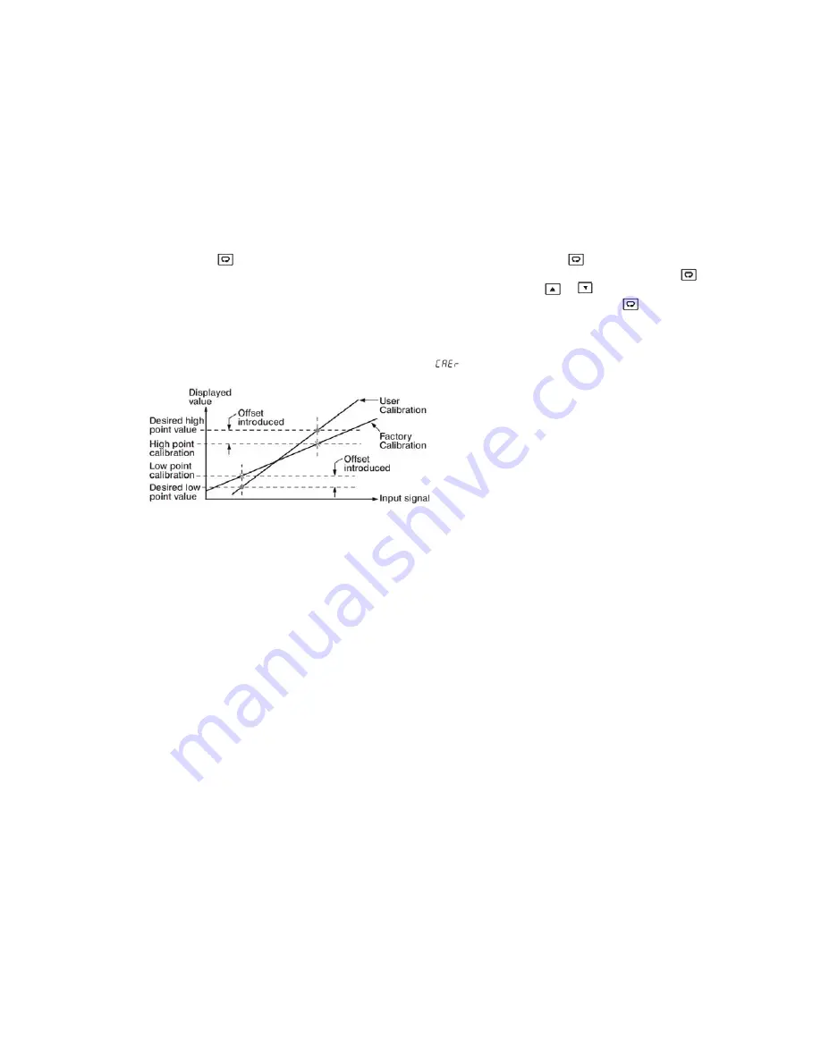
5.9 User Calibration: User calibration allows the user to offset the permanent factory calibration. There are two parameters:
Offset Low (OFTL) and Offset High (OFTH) for adjustment to correct an error in the process value.
There are two parameters for the sensor input. These two signal values are CALO and CAHI. The input signal low and high values
are to be entered in the CALO and CAHI parameters respectively.
Press and hold the
key until the setup Menu page is obtained. Then, press and release the
key to navigate to the
calibration low parameter OFTL. Send your low signal to the sensor input of the controller, then press and release the
key. If
the process value (the upper display) is different from the input signal, the user can use
and
keys to change the OFTL
value (the lower display) until the process value is equal to the value the user needs. Press and hold the
key for 5 seconds to
complete the low point calibration. A similar procedure is applied for high scale calibration.
As shown below, the two points OFTL and OFTH construct a straight line. For the purpose of accuracy, it is best to calibrate with the
two points as far apart as possible. After the user calibration is complete, the input type will be stored in the memory. If the input
type is changed, a calibration error will occur and an error code
is displayed.
5.10 Digital Filter:
In certain applications the process value is too unstable to be read. To improve this, a programmable low pass filter
incorporated in the controller can be used. This is a first order filter with a time constant specified by the FILT parameter. A value of
0.5 seconds is used as a factory default. Adjust FILT to change the time constant from 0 to 60 seconds. 0 seconds represents no
filter applied to the input signal.
5.11 Failure Transfer:
The controller will enter failure mode if one of the following conditions occurs.
1.
SBER error occurs due to an input sensor break, input current below 1mA for 4-20mA or input voltage below 0.25V for 1-5V.
2.
ADER error occurs due to the A-D converter of the controller fails. Output 1 and Output 2 will perform the failure transfer (O1.ft &
O2.ft) function as the controller enters failure mode.
3.
Alarm Failure Transfer: An alarm failure transfer is activated as the controller enters failure mode. After that, the alarm output will
transfer to the ON or OFF state which is determined by the set value of A1FT, A2FT, A3FT, and A4FT.
5.12 Soft-Start:
The controller has soft start function to limit the control output on out1 and out2 for a programmable time SFT or up to
a programmed threshold value SFTH. The first of two will terminate soft start function and the normal PID control begins. This
function is useful for effects such as suppressing the heater output during equipment startup, or lightening the load.
Note:
In Profile Version controllers If PFR is set to other than SP1 then the profile function will continue with the set parameter
during power recovery. If PFR is set to SP1 then the profile will continue to run with soft start parameters during power recovery.
There are 5 parameters available for soft start function. They are as below.
1. SFt:
Soft start time. If SFt
≠
0, then the Soft start function will be enabled. The SFt can be set in the form of Hour: Minute. The
range can be set is 00.00 to 99:59.
2. SFL1:
Soft Start output limit for output 1. It can be set from PL1L to PL1H.
3. SFL2:
Soft Start output limit for output 2. It can be set from PL2L to PL2H.
4. SFtH:
Soft start threshold value. The Soft start will be aborted when the process value is greater than or equal to SFtH.
5. SFtR:
Soft start time. It will show the remaining time of soft start when it is running.


