background image

Gyro data 1/2 2/2

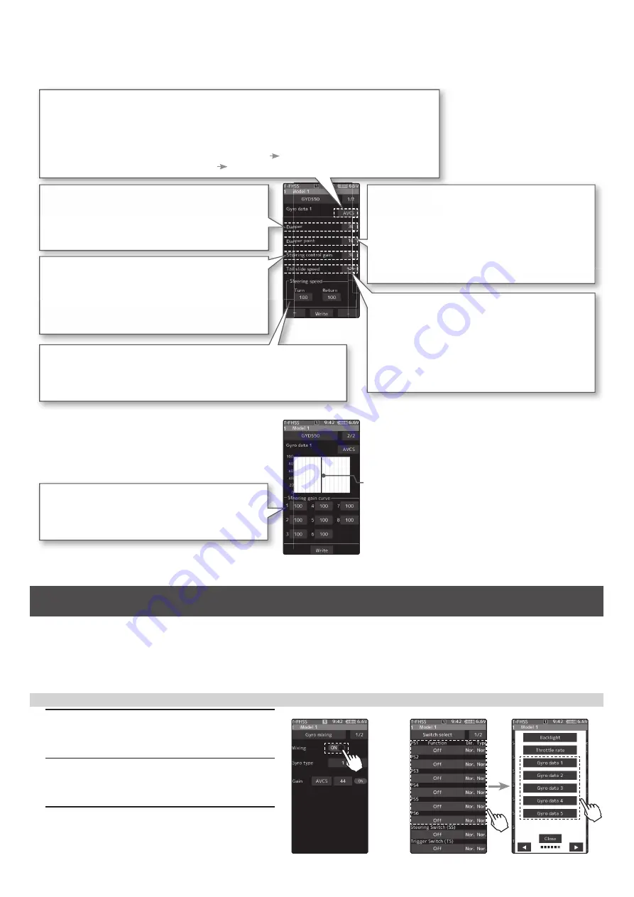
  The gyro data setting screen has two pages, and the page can be a switch with the page switching button on the 

upper right.  Also, data can be set independently in each gyro operation mode (normal / AVCS).

AVCS and normal mode change button

The AVCS / NORMAL modes setting.

The gyro has 2 operating modes: NORMAL mode and AVCS mode. 
In the AVCS mode, gyro control is fi rmer.
* The feel of operation is different, choose your favorite mode.
* NORMAL: The driver needs to perform counter-steer 

 Operation opposite to the turn direction.

* AVCS: The gyro performs countersteer 

 Steer in the turn direction.

Damper

Hunting suppression

  The higher the value, the stronger the hunting 

suppression. However, it will feel like the servo 
response has worsened.

Damper point

Adjust the servo response due to the ef-
fect of the damper against the gyro effect.

* The smaller the value, the stronger the infl uence 

of the Damper and the slower the servo speed.

* The higher the value, the slower the Damper will 

operate and the better the response, but the more 
likely it is that hunting will occur.

Tail slide speed

Adjust the speed of the tail slide (shake 
the tail) when driving.

* Decreasing the numer ical value decreases 

the speed of the tail slide, and increasing the 
numerical value increases the speed.

* Effective for adjusting the tail slide amount during 

steering operation.

Steering control gain

Adjustment of intervention ratio of steer-
ing operation to gyro control.

  When the numerical value is increased, the 

steering operation of the driver is largely refl ected.

* The steering response feels fast.

Steering speed

The function to adjust servo speed for steering operation 
(same the function as servo speed of the transmitter).

* The smaller the value, the slower the servo speed.

Steering gain curve

Eight points of gain can be set up to the 
endpoint based on neutral.

* It is set in conjunction with left-right symmetry.

* The ver tical cursor line moves in 

conjunction with the operation of the 
steering.

Gyro data screen 

1/2

Gyro data screen 

2/2

Additional function / Gyro data switching function

*\URGDWDFDQEHVZLWFKHGZLWKWKHSXVKVZLWFKRUWULPOHYHUGLDORIWKHWUDQVPLWWHU8SWRJ\URGDWD
$OVRLWLVSRVVLEOHWRFKDQJHJ\URGDWDDFFRUGLQJWRWKHFRQGLWLRQRIWKHWUDQVPLWWHU8SWRJ\URGDWD

-   Connect the gyro to the S.BUS2 terminal of the receiver. 

-  The gyro mixing function must be enabled.

1

  On the Gyro mixing 1/2 screen, set the func-

tion to ON.

2

  On the Switch select screen, select the switch 

you want to use for data switching.

3

 On the function selection screen, assign the 

gyro data to be used from [Gyro data 1] to 

[Gyro data 5].

When switching with the push switch

Gyro mixing screen  1/2

Switch select screen 

Содержание T7PXR

Страница 1: ... the microSD card with FUTABA folder that contained the update software into the SD card slot on your T7PXR T7PX T7XC radio transmitter 6 Turn on the transmitter power while pressing down the HOME button The update screen appears on the LCD display of your T7PXR T7PX T7XC and the software update is started 7 When the software update is completed Completed message is shown on the LCD display of you...

Страница 2: ...sed with the display switch DSP Turn on the receiver power switch 1 Gyro read When you open the Gyro Link screen from the Accessory menu or Custom menu the connection method selec tion screen is displayed Tap the button according to the connection method between the gyro and the receiver The Gyro type and currently set contents are read Using the Gyro Link function Additional function Wireless Gyr...

Страница 3: ...ta In the case of selection type touch the item to switch the data Display data list Data settings Basic setting screen Gyro reading screen Gyro data screen 1 2 2 2 Basic setting In the T FHSS SR mode the servo position will not adjust until Write even if the Limit and Neutral offset functions are adjusted with and Response mode Gyro sensor response setting Low Middle High speeds up response In hi...

Страница 4: ...umerical value increases the speed Effective for adjusting the tail slide amount during steering operation Steering control gain Adjustment of intervention ratio of steer ing operation to gyro control When the numerical value is increased the steering operation of the driver is largely reflected The steering response feels fast Steering speed The function to adjust servo speed for steering operatio...

Страница 5: ...ect the switch you want to use for data switching 3 On the function selection screen assign the Gyro data 1 On the Gyro mixing 1 2 screen set the func tion to ON 2 Display 2 2 of the gyro mixing screen A list of conditions and gyro data is displayed Tap the condition to be set 3 Select the gyro data to be assigned to the condition When switching with the push switch When switching with the push sw...

Страница 6: ...ate Preparation Display the D R ATL screen from the linkage menu or custom menu 1 Function ON OFF Tap Throttle rate ON or OFF to select ON OFF OFF Throttle rate function OFF ON Throttle rate function ON Throttle rate adjustment Additional function Throttle rate Change of throttle speed screen Change of steering mixing rate KDQJH RI VWHHULQJ PL LQJ UDWHV VRIWZDUH YHUVLRQV 9HU WR WKH VWHHULQJ PL UDW...

Страница 7: ...WHU 1 Change home screen display Tap Normal or Instrument panel on the home screen display to select In the meter displayed on the home screen the white pointer indicates the maximum value and the red arrow indicates the current value 1 Meter type setting Select Instrument panel in the home screen display settings Tap the meter to be set on the home screen to select it Use the following procedure ...

Страница 8: ...ED 4 Release the Link SW LED 2 seconds solid Blink Touch the Close button on the link screen of the transmitter to cancel the link mode 5 Completed with LED solid the receiver If there are many T FHSS Mini Z systems turned on in close proximity your receiver might have difficulty establishing a link to your transmitter This is a rare occurrence How ever should another T FHSS Mini Z transmitter rec...

Страница 9: ...tion allows you to assign a fifteen character name to each condition 1 From the Condition Name list tap the condition button whose name you want to change 2 Since the condition name setting screen is displayed edit the name 3 Tap the title button Condition name to return to the condition screen Condition name This function copies condition data to other conditions 1 Tap the copy condition button Th...

Страница 10: ...on 2 by operating the switch If you select Condition 1 to Condition 4 for each switch you can change to the condition assigned by each switch operation This function can change the condition by trim or dial By operating Trim or Dial you can change the condition as Condition 1 2 3 4 or 4 3 2 1 1 Tap the Trim Dial select button to display the Trim Dial select screen The Trim Dial select screen can a...

Страница 11: ...3 0 KHQ WKH WULP RU WKH GLDO LV RSHUDWHG WKH YDOXH RI WKH IXQFWLRQ LV GLVSOD HG IRU D IHZ VHFRQGV DW WKH WRS RI the screen Example The trim dial is assigned to the gyro mixing function The value of the gyro gain is indicated to the top of the screen for several seconds Additional function MC ESC Link MC970CR 7KH 0 5 KDV EHHQ DGGHG WR WKH 0 6 OLQN IXQFWLRQ RI XWDED 6 SDUDPHWHU FKDQJH 0 5 LV DYDLODE...

Страница 12: ...XSSRUW WR FKDQJH 65 PRGH RI 36 Before the improvement 6 XV VHUYR VFUHHQ RI YHUVLRQ 9 WR 9 YHQ LI D VHUYR WKDW LV QRW FRPSDWLEOH ZLWK 65 PRGH LV FRQQHFWHG RX FDQ VZLWFK WKH VHUYR WR 65 PRGH EXW WKH VHUYR ZLOO QRW ZRUN DQG GDP DJHG LI RX VZLWFK LW WR 65 PRGH I RX FRQQHFW D VHUYR WKDW LV QRW FRPSDWLEOH ZLWK 65 PRGH WKH VFUHHQ IRUELGV RX VZLWFK LQJ LW WR 65 PRGH After the improvement 6 XV VHUYR VFUHHQ...

Страница 13: ...unication For safety in case of electric car boat please set with driving wheel boat propeller not touching the road surface water surface Also in the case of an internal combustion engine car boat be sure to stop the engine before entering wireless set up mode NOTE RU VDIHW UHDVRQV LW LV QRW SRVVLEOH WR FKDQJH EHWZHHQ QRUPDO PRGH DQG 65 PRGH ZLWK ZLUHOHVV VHW WLQJ 7R FKDQJH WKH PRGH FRQQHFW WKH V...

Страница 14: ...n Menu screen Accessory menu screen S Bus servo 1 Tap the Read button The notes on wireless setting are displayed Tap the Close button Once this screen is displayed it will not be displayed again until you turn the power back on 2 Touch the channel in which the servo to be set is connected and read the setting data from the servo Communication port T7PX communication port conventional wired settin...

Страница 15: ...TABA is created Insert the micro SD card that contains the FUTABA folder into the T7PX see page 31 of the manual Connection between T7PX and receiver Preparing for update 1 Hold down the Link switch first and turn ON the receiver After the LED flashes red once release the Link switch and then press it again As you continue holding down the Link switch the LED starts flashing red and green Once flashin...

Страница 16: ...VH LW H FHSW ZKHQ GDWD LV EURNHQ 1 While pressing the PS6 switch turn on the transmitter power How to Initialize 2 A confirmation screen Caution The current model data will be initialized Sure will be displayed 3 Touch Yes to carry out initialization and turn off the power Since the current model data will be initialized please re set the data and check the operation carefully before use To cancel ...

Отзывы: