Fusion3 Design F306 Generation I Скачать руководство пользователя страница 51

51 


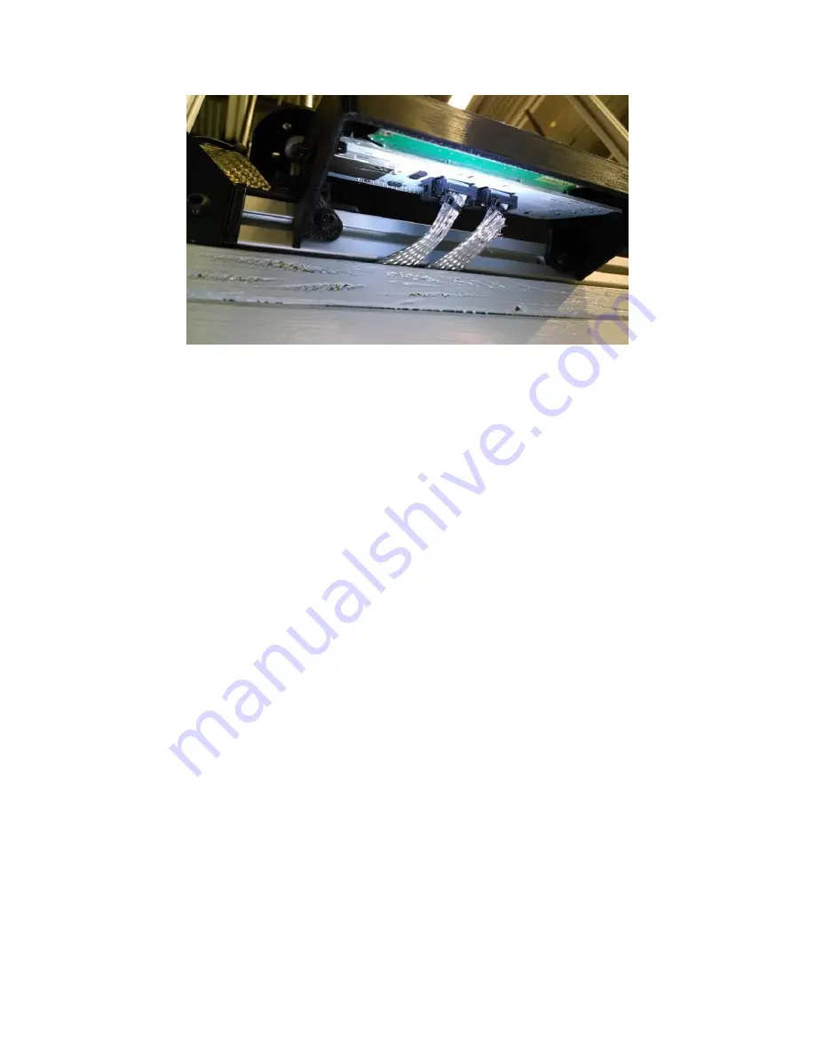
Figure 54: Installing control panel cables 

If desired, remove the protective plastic from the LCD screen. 

Power Up 

Now we are ready to power your F306 up for the first time! Remove the power cord from its bag in the small box 
and plug it into the socket next to the power supply on the left side of the machine. Connect the other end to a 3-
prong outlet. 

When you flip the power switch, these things should happen:  


The internal PSU fan should begin spinning quietly. 


The white LED lights should come on. 


The screen should light up, and after a moment text should appear. 


A green LED should illuminate on the control board. 


The print head cooling fan should begin running. 
 

IF ANY OF THESE THINGS DO NOT HAPPEN, POWER DOWN IMMEDIATELY AND CONTACT SUPPORT 

Check Z Axis 

With your F306 powered up, we can now check the Z axis for proper movement. 

Reach underneath the print bed and grasp the Z axis belt with your hand. Slowly move the belt in the direction that 
lifts the bed up. Continue to move the belt by hand until the bed reaches the top of its travel, 

but be careful not to 

collide with the print head!


Содержание F306 Generation I

Страница 1: ...54 APPENDIX C Notes for Dual Extrusion Owners 58 2 Introduction Thank you for purchasing Fusion3 s F306 3D printer This manual is designed to familiarize you with your F306 and its use and give you t...

Страница 2: ...components 2 Your First Print This section will guide you through the steps to get your F306 printing for the first time We highly recommend using the included roll of PLA filament and printing the pr...

Страница 3: ...h the head and bed are up to temperature your F306 will begin the print by dropping the bed about 10mm It will then pump out about 30mm of filament This is to ensure the melt chamber in the print head...

Страница 4: ...into a list of commands that the F306 will follow to build the object The central piece of software in this process is called the slicer While there are many slicers available to perform this task th...

Страница 5: ...figuration files off of your SD card to your local hard drive In Simplify in the Processes section click Add In the dialog window that appears you will see an Import button at the top Click that navig...

Страница 6: ...will give you the ability to select English or metric units Please leave the units as metric as English units appear to be broken in the software Where Can I Get Models to Print If you don t want to d...

Страница 7: ...7 4 General Info Hardware 4 1 Machine Overview Figure 5 Front View Figure 6 Side View...

Страница 8: ...8 Figure 7 Axes Layout Figure 8 Control Board Detail...

Страница 9: ...9 Figure 9 Print Head Detail Figure 10 Extruder Cold End Detail...

Страница 10: ...omplete while a print is running 7 Print elapsed time 8 Message row 4 2 Precautions Moving Components By Hand If you need to move the print head X crossbar or Z axis by hand you should do this with yo...

Страница 11: ...ce the print head and cause misalignment Figure 13 Moving the Z Axis by Hand IMPORTANT DO NOT move any part of the machine while it is powered completely off When powered off the motors will act as ge...

Страница 12: ...machine up Take care not to catch the control panel on you as you lift Optionally you can remove the control panel from the printer for transport This eliminates the chance of inadvertent damage If y...

Страница 13: ...re to Buy We recommend buying filament directly from Fusion3 The material we supply has been extensively tested and tuned on our equipment Our default printing profiles are set up for these materials...

Страница 14: ...erature Bed sets bed temperature Fan speed controls speed of cooling fan 255 max power Other settings on this menu can be ignored o Motion can ignore this menu Card Menu shows list of all gcode files...

Страница 15: ...er of folds until the total thickness is 0 008 0 009 since paper can compress under the nozzle You may also need to try different weights of paper to get the right thickness If you lose your feeler ga...

Страница 16: ...ously melted plastic or any bends It can help to trim the end at an angle as shown This will help the end feed through the extruder system more easily Figure 18 Trim the End of the Filament Install th...

Страница 17: ...and select the load filament option The print head will begin heating and you will see instructions on screen to load the filament into the extruder Manual Loading Navigate to the temperature control...

Страница 18: ...18 Figure 20 Filament Fed Across Hobbed Gear Figure 21 Disengaging the Idler Bar Springs...

Страница 19: ...may attempt to feed the filament too quickly into the print head and damage the system Manual Loading While the print head is heating turn the large gear on the side of the extruder by hand to feed t...

Страница 20: ...a couple days is not a problem But you don t want to leave a roll out in the open if you aren t going to use it for an entire week Filament that has absorbed moisture will not print nearly as well as...

Страница 21: ...g it with the spray bottle and smearing it around with your hand As you use your printer you will get a feel for when to do this and when to put fresh glue down Cleaning Off Glue from a Previous Print...

Страница 22: ...file you just prepared in Simplify Press the scroll wheel to select the file The rest is automatic Your F306 will automatically home and heat the bed and print head to the correct temperature The prin...

Страница 23: ...under the part All Materials After removing the part remove the priming skirt that is printed around the part and the priming dump done at the home position It is also good practice to inspect the pri...

Страница 24: ...ome more advanced techniques 6 1 Simplify3D Guidelines While Simplify3D is easy to use there are certain rules to keep in mind that will ensure you get the best results Part Orientation The most impor...

Страница 25: ...le we have satisfied our criteria for a large face to sit on the build plate However the entire upper flange is unsupported and will not print properly without support structure In this orientation we...

Страница 26: ...u to download and these can be a great way to get printing quickly However the quality of the models can vary widely This section will cover the most common issues and how to fix them Missing Faces In...

Страница 27: ...ser input needed It does require a Microsoft online account however Model Does Not Sit Flat Some models have a very slight tilt in one or more axes and even though they appear to sit flat on the build...

Страница 28: ...e STL What we see is that the creator of this file most likely took an off the shelf model of a shoe and a model of a leg and simply put them together There is a lot of internal geometry like the toes...

Страница 29: ...ify figure out where it s needed It may sometimes generate support where it s not actually needed but that is the safer option More detail on Simplify s support generation can be found on their tutori...

Страница 30: ...d off for this part Simplify would not give you an error message when you prepared the part for printing It assumes you know when support is or is not needed Speed vs Quality The default slicing setti...

Страница 31: ...Layer Tab Figure 35 Print Speed is set on the Other tab Layer Height Limits Too tall of a layer height will result in poor intra layer adhesion because they are not squashed together enough In general...

Страница 32: ...ptoms of improper first layer height may include The part is not sticking to the bed on the first 1 3 layers first layer is too tall Obvious gaps between the extrusion beads are visible first layer is...

Страница 33: ...the print head and bed can be so close than no plastic is extruded at all This can cause problems with the extruder slipping or jamming To correct this the corner bolts should be tightened threaded i...

Страница 34: ...oat bed with light coating of glue stick For slow prints or prints with many successive retractions reduce temperature to 200o C Increasing print speed will need a relatively large increase in tempera...

Страница 35: ...rom liquid to solid This contracting causes the molten and cooling upper layers to exert a pulling force on the lower layers which have already solidified If enough of this pulling force is generated...

Страница 36: ...o prevent it from occurring again If you merely clear the jam without diagnosing the root cause the jam will likely occur again in short order Thermal Jams Thermal jams primarily occur at the print he...

Страница 37: ...ament inspect the remainder of the spool for additional imperfections 5 Debris on the surface of the filament or in the filament very rare is fed into the print head the debris is large enough to bloc...

Страница 38: ...or assistance in working with other materials In general we re able to provide a good starting point for further experimentation if not a complete and tested material profile 6 9 Different Print Heads...

Страница 39: ...y will go They will stop turning when the tips of the bolts make contact with the extruder motor Figure 39 Tips of Bolts Bottomed Out on Motor Figures 39 40 Rev 1 idler bar left and rev 2 idler bar ri...

Страница 40: ...s should be fairly tight but not so tight they hum like a guitar string Recommended service interval once per month or every 40 hours of run time Figure 40 Checking XY Drive Cable Tension If the cable...

Страница 41: ...e moveable idlers To do this you will need a 4mm hex wrench and 10mm socket Loosen the bolt on one of the idlers and slide it in the slot to achieve proper tension Then re tighten the bolt Figure 43 A...

Страница 42: ...tt one end of the tape measure into the corner made by the X axis and the Y carriage plate Make sure it s seated in a repeatable manner Measure to the middle bolt on the front wrap brackets Measuremen...

Страница 43: ...d away from the nozzle Cleaning beyond this is more a matter of cosmetics than functionality Recommended service interval after every print Check Heat Break Tightness Periodically it s a good idea to...

Страница 44: ...If you haven t removed the print head and you notice the heater block is no longer square it may have come loose Removal Installation This video shows how to completely remove and disconnect your pri...

Страница 45: ...packing materials in case you need to return your F306 to us they fold flat for easy storage Remove the banding straps or plastic wrap that holds the box onto the pallet Remove the lid of the box by...

Страница 46: ...46 Figure 46 Top Foam Blocks Now you should be able to remove the sleeve from around the printer Lift straight up taking care not to hit the F306 as you lift The sleeve folds flat for easy storage...

Страница 47: ...blocks Set it down on a firm stable work surface Refer to section 4 2 for lifting and carrying instructions Remove the small box from the cardboard tray This is attached with spray adhesive to keep it...

Страница 48: ...e and remove the spare plate Remove the zip ties that hold the X axis and print head in place They are marked with blue tape There are two on the left Y carriage and two on the X carriage Figure 50 Cu...

Страница 49: ...and slowly move it through its entire range of motion in X and Y You should feel little or no change in resistance or binding as you move the carriage IMPORTANT Since we are moving the axes while the...

Страница 50: ...unit onto the frame Use the 4mm hex drive included in your toolkit since a ball end drive is needed for this step Tighten the bolts only slightly more than finger tight Position the control panel as f...

Страница 51: ...spinning quietly The white LED lights should come on The screen should light up and after a moment text should appear A green LED should illuminate on the control board The print head cooling fan shou...

Страница 52: ...bottom of its range of travel is normal with a gradual decrease as the bed moves up With the bed at the top of its travel check the distance from the top of the adjacent beam to the steel plate near...

Страница 53: ...An out of level platform possibly indicates rough treatment during shipping so we ll want to guide you through some additional checks by phone If the platform is level congratulations Your F306 is no...

Страница 54: ...t First make a new tab in the worksheet and copy the template to the new sheet This way the template stays the same Step 1 Measure Filament Diameter The first step is to measure the diameter of the fi...

Страница 55: ...will then calculate an average diameter which you input into Simplify as shown below Figure 59 Input Filament Diameter Step 2 Prepare test object Next set up Simplify to slice a simple object with the...

Страница 56: ...e wall thickness as bad measurements will result in poor calibration You want to grab only the top 3 6 layers in the jaws of the calipers and use very light pressure so as not to crush the wall Once y...

Страница 57: ...57 In general you should be able to get within 1 of the correct flow rate with 3 trials...

Страница 58: ...ds The additional extruder behaves exactly the same as the first The print head assembly consists of 2 E3D V6 print heads 2 blowers and the print head bracket The primary extruder is called E0 and the...

Страница 59: ...ere are 4 scripts in total a load script for each print head and an unload script for each print head These work similarly to the scripts for the single head systems Simplify3D Depending on what your...

Страница 60: ...ing with multiple extruders You ll need to scroll down to workflow for 2 colors Basically you have 2 STLs one for each color You add 2 printing processes in Simplify assign the _0 profile to process 1...

Отзывы: