003
IN
ST
AL
LA
TIO
N
INSTALLATION
IF ANY MODIFICATION TO THE VESSEL IS REQUIRED, SUCH AS DRILLING
HOLES ETC FUSION RECOMMENDS CONSULTATION WITH YOUR BOAT
DEALER OR MANUFACTURER BEFOREHAND.
Caution:
The MS-RA200 is designed for vessels with a 12V DC Negative ground electrical system
ELECTRICAL WIRING
Note:
Appropriate mounting is very important to
ensure correct operation. Select a location that allows
both free/open airflow around rear of chassis, whilst
minimizing exposure to moisture. Allow adequate
room at the rear of the unit for the cable looms
(approx 2”).
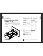
Create mounting hole for product and drill Screw
Pilot Holes.
Refer to mounting template included with product
or download from www.fusionelectronics.com
Fit mounting gasket
Insert the unit into the mounting hole
Use the supplied 4 x self tapping screws, to affix
the unit into position.
Attach screw covers
»
»
»
»
»
Mounting Gasket
Screw Covers
Screw Pilot Hole
Mounting Hole
020
SP
ECS
&
L
ICE
NS
IN
G
PUBLISHED BY FUSION ELECTRONICS LIMITED. © Copyright 2010 by FUSION Electronics Limited. All rights reserved. Specifications and design
are subject to change without notice. YOU CAN HELP PROTECT THE ENVIRONMENT Please remember to respect the local regulations:
Hand in the non-working electrical equipment to an appropriate waste disposal centre. v4.2
SPECIFICATIONS
CHASSIS DIMENSIONS
Depth 93mm - 3-5/8”
Width 130mm – 5-1/16”
Height 50mm – 2”
FACE PLATE DIMENSIONS
Depth 29mm – 1-1/8”
Width 157mm – 6-3/16”
Height 68mm – 2-11/16”
OPERATING VOLTAGE:
10 – 16VDC Negative ground
FUSE RATING:
15 Amp
OUTPUT POWER:
50 Watts x 4 (Max)
SPEAKER IMPEDANCE:
4 Ohms per channel
PRE – OUTPUT VOLTAGE:
3V
SPECIFICATIONS AND LICENSING
LICENSING
Apple, the Apple logo, iPod, iPhone, ‘Made for iPod’ and ‘Works
with iPhone’ are Trademarks of Apple Computer, Inc., registered in
the U.S. and other countries.
© 2007 SIRIUS Satellite Radio Inc. “SIRIUS” and the SIRIUS dog logo
are trademarks of Sirius Satellite Radio Inc. All rights reserved.
TUNING RANGE
EUROPE AND AUSTRALASIA:
AM Radio
Frequency Range:
522 – 1620 MHz
Frequency step:
9 kHz
FM Radio
Frequency Range:
87.5 – 108 MHz
Frequency step:
100 kHz
FM Radio
Frequency Range:
87.5 – 107.9 MHz
Frequency step:
200 kHz
AM Radio
Frequency Range:
530 – 1710 MHz
Frequency step:
10 kHz
USA
FM Radio
Frequency Range:
70 – 90 MHz
Frequency step:
50 kHz
AM Radio
Frequency Range:
522 – 1620 MHz
Frequency step:
9 kHz
JAPAN
VHF TUNING RANGE
All Regions:
Frequency Range:
156 – 164 MHz

