background image

5.  VECTOR (S57) CHARTS

5-5

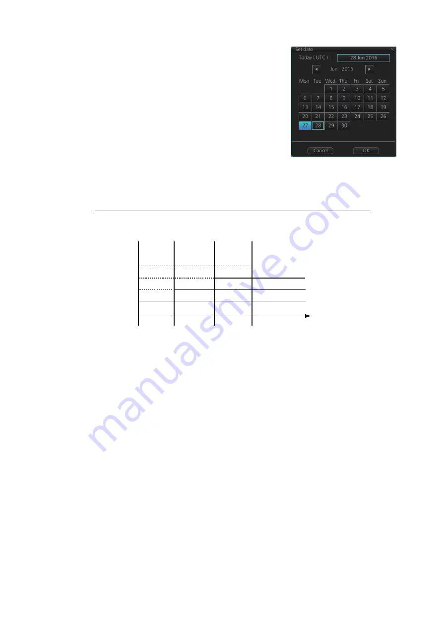
3. Click the date button to show the [Set date] dialog 

box.

4. Select the appropriate date from the calendar, 

then click [OK] to close the [Set date] dialog box 
and return to the [Viewing Dates] dialog box. 

5. Click [Close].
6. Check the appropriate charts, then access the 

Viewing Dates dialog again (see step 1).

7. Select [AUTO - Today] to show the current date’s 

chart.

8. Click [Close].

5.2.3

About chart viewing date dependency of S57 standard

How the issue date of updates changes the visibility of the changes

Study the example below to understand the behavior of updates relative to date.

The figure above shows how updates are dependent Chart viewing dates set in Dis-
play/Approved date settings by user. Actions 1 to 4 areas as follows:

1. Base cell including three updates is converted into SENC. Display date is set as 

current date of the system. Approve date has to be set to current date.

2. The date in which update 1 was issued. Display and Approved dates have to be 

set to correct date in order to see the chart with update 1.

3. The date in which update 2 was issued. Display and Approved dates have to be 

set to correct date in order to see the chart with update 1 and update 2. 

4. The date in which update 3 was issued. Display and Approve dates have to be set 

to correct date in order to see the chart with update 1, update 2 and update 3. 

Note 1: 

 In order to display charts with correct updated situation, always use current 

date during your voyage. If your voyage lasts more than one week, set current date at 
least once per week during your voyage.

Note 2: 

In order to display charts with correct updated situation during route planning, 

always use planned date of each waypoint to check your plan.

1               2                  3                4

Update 3

Update 2

Update 1

Base cell

Date

Содержание FMD3100

Страница 1: ...www furuno com OPERATOR S MANUAL Model FMD 3100 ELECTRONIC CHART DISPLAY AND INFORMATION SYSTEM ECDIS ...

Страница 2: ...al is elemental chlorine free FURUNO Authorized Distributor Dealer 9 52 Ashihara cho Nishinomiya 662 8580 JAPAN A FEB 2014 Printed in Japan All rights reserved E DEC 05 2017 Pub No OME 44840 E GREG FMD 3100 0 0 0 1 7 8 7 5 5 1 4 ...

Страница 3: ...bols can increase when the other countries make their own recycle symbols in the future This manual has been authored with simplified grammar to meet the needs of international users The operator of this equipment must read and follow the descriptions in this manual Wrong oper ation or maintenance can cancel the warranty or cause injury Do not copy any part of this manual without written permissio...

Страница 4: ...e or electrical shock can result Keep the equipment away from areas where contact with water is likely Fire or electrical shock can result if water gets into the equipment WARNING The operator must read the safety instructions before attempting to operate the equipment Indicates a potentially hazardous situation which if not avoided could result in death or serious injury Indicates a potentially h...

Страница 5: ...he settings for a profile 1 14 1 16 5 How to restore default settings to a profile 1 14 1 17 How to View ECDIS Software Version No ECDIS System Information and Operator s Manual 1 16 1 18 Split Screen 1 17 1 18 1 How to activate deactivate the split screen 1 17 1 18 2 Function availability in split screen operation 1 18 1 18 3 Split screen usage characteristics 1 18 1 19 Tips 1 19 1 20 Printer Inf...

Страница 6: ... Install Public Keys for ENC Charts 3 2 3 3 How to Install ENC Licenses Charts 3 3 3 3 1 How to install an ENC license 3 3 3 3 2 How to install ENC charts 3 4 3 4 How to Install ARCS Licenses Charts 3 6 3 4 1 How to install an ARCS license 3 6 3 4 2 How to install ARCS charts 3 7 3 5 How to Delete ENC ARCS Licenses 3 9 3 6 How to Find ENC Chart Manufacturer Info 3 9 3 7 How to Install C MAP Charts...

Страница 7: ...e for shallow contour safety depth safety contour and deep contour 4 1 4 2 2 Basic Setting menu 4 3 4 2 3 Chart Display menu 4 4 4 2 4 Display base 4 5 4 3 How to Control Visibility of Symbols Features 4 6 4 3 1 General page 4 6 4 3 2 Tracking page 4 7 4 3 3 Route page 4 9 4 3 4 Mariner page 4 10 4 3 5 Targets page 4 11 4 4 How to Control Predefined IMO Chart Display Settings 4 12 5 VECTOR S57 CHA...

Страница 8: ...ute Planning Overview 9 1 9 2 Main Menu for Route Planning 9 2 9 3 How Route Data is Synced 9 2 9 4 How to Create a New Route 9 3 9 4 1 How to use the Waypoints page 9 5 9 4 2 How to use the User Chart page 9 6 9 4 3 How to use the Optimize page 9 7 9 4 4 How to use the Alert Parameters page 9 8 9 4 5 How to use the Check Results page 9 9 9 5 How to Modify an Existing Route 9 10 9 5 1 How to chang...

Страница 9: ...to Start Route Monitoring 11 1 11 2 How to Stop Monitoring a Route Manual Auto 11 3 11 3 How to Select What Parts of a Route to Display 11 4 11 4 How to View Waypoint Information 11 4 11 5 How to View Linked User Chart Information 11 5 11 6 How to View User Chart Object Information in Route Monitoring 11 6 11 7 How to Change Monitored Route to Planned Route 11 6 11 8 How to Use Instant Track to Re...

Страница 10: ...elect past position reference 13 7 13 6 2 Past position point attributes 13 7 13 7 How to set the TT Source 13 8 13 7 1 TT source for configurations compliant with the latest regulations 13 8 13 7 2 TT source for non compliant configurations 13 9 14 AIS TARGET FUNCTIONS 14 1 14 1 Introduction 14 1 14 2 AIS Symbols 14 2 14 3 Voyage Data 14 5 14 4 How to Show Hide AIS Targets 14 6 14 5 How to Filter...

Страница 11: ...7 5 6 Ocean current display 17 7 17 6 Weather Spot Information 17 8 17 7 Summary of Weather Overlay Viewability Operability and Operating Mode 17 8 18 NAVIGATION SENSORS 18 1 18 1 CCRS 18 1 18 2 How to Select Navigation Sensors 18 2 18 2 1 Sensors menu description 18 2 18 3 Source of Position 18 5 18 4 CCRP Primary and Secondary Positions of Own Ship 18 6 18 5 Source of Navigation Data 18 7 18 6 S...

Страница 12: ...22 2 File Export 22 2 22 3 File Import 22 3 22 4 File Maintenance 22 4 22 5 Alert Setting 22 5 22 6 Self Test 22 7 22 7 Data Sharing 22 8 22 8 Customize 22 9 22 9 Display Test 22 10 22 10Keyboard Test 22 11 22 11Screenshots 22 12 22 11 1How to export screenshots 22 13 22 11 2How to delete screenshots from the PCU 22 13 22 11 3How to print screenshots 22 13 22 12User Default 22 14 22 13CCRP 22 15 2...

Страница 13: ...50074 03 xx xx minor change CE declaration With regards to CE declarations please refer to our website www furuno com for further infor mation about RoHS conformity declarations Complies with IMO MSC 232 82 IMO A 694 17 IEC 61162 450 Ed 1 IEC 61174 Ed 4 IEC 61162 1 Ed 4 IEC 61162 2 Ed 1 IEC 62288 Ed 2 IEC 60945 Ed 4 Continuous monitoring of ship s position through multi sensor Kalman filter proces...

Страница 14: ...3 ed 1 2 0 IHO CDS S 64 Ed 2 0 0 S 64 Ed 3 0 1 When you update a chart The PC and medium USB flash memory etc used to download and hold an update for an ex isting chart or a new chart may be infected with a virus Check the PC and the medium for viruses with a commercial virus checker BEFORE you connect them to the ECDIS Be sure the virus checker contains the latest virus definition files Network c...

Страница 15: ...Serial Interface 4 ports IEC 61162 1 2x2 AIS GYRO IEC 61162 1x2 GPS LOG Switching Hub HUB 100 Sensor Adapter MC 3020D Sensor Adapter MC 3030D Serial interface Digital IN interface Digital OUT interface Sensor Adapter MC 3000S Intelligent Hub HUB 3000 Radar 1 Radar Connection Box RCB 002 AC DC Power Supply Unit PR 240 Radar 2 100 230 VAC Gateway network equipment radar ECDIS etc 1 Use full HD monit...

Страница 16: ...or Adapter MC 3020D Sensor Adapter MC 3030D Serial interface Digital IN interface Digital OUT interface Sensor Adapter MC 3000S PANEL COMPUTER UNIT PCU 3000 PANEL COMPUTER UNIT PCU 3000 Same equip ment and power supply as shown left Intelligent Hub HUB 3000 100 230 VAC 100 115 200 230 VAC 1Ø 50 60 Hz 24 VDC Radar 1 Radar Connection Box RCB 002 AC DC Power Supply Unit PR 240 Radar 2 External Monito...

Страница 17: ...ave a FURUNO service engineer check the set 3 Brilliance Control Adjusts the display brilliance See section 1 7 4 Brilliance Status Indicates if the brilliance is within or outside of the ECDIS standard See section 1 7 5 Power Switch Turns the power on or off See section 1 5 Note 1 To keep the system stable restart the PCU at least once every two weeks Note 2 If the ambient temperature is less tha...

Страница 18: ...5 DVI D Out DVI I RGB Out No use 2 x IEC 61162 1 2 x IEC 61161 2 1 Pull and turn the locking pin clockwise to unlock it Tilt the display to desired angle Turn the locking pin counter clockwise and push it to insert it into the bracket If the pin does not insert tilt the display forward or backward slightly until you find the locked position Turn pin counterclockwise to insert pin in bracket Lockin...

Страница 19: ...ccurs also connect the USB power connec tor cable shown to the right to the PCU to draw additional power 1 5 How to Turn the Power On or Off The power switch on the PCU illuminates in red when the power is connected and the PCU is turned off To turn the power on push the power switch until the lamp in the switch illuminates in green To turn the power off press and hold down the power switch until ...

Страница 20: ...BRILL control on the Control Unit Note 2 If the display cannot be seen when switching from a Night to Day palette push and hold the right button approx 2 seconds to switch to the dusk gray mode Note 3 The color palette setting may not get synchronized among ECDIS units se lected for synchronization if a unit is being booted during the selection of the color pal ette If this occurs wait until all E...

Страница 21: ...the BRILL button on the InstantAccess bar to show the brilliance adjustment window 2 For coarse adjustment place the cursor at the approximate location on the slide bar where you want to set the brilliance then click to change the brilliance For fine adjustment place the cursor on the slide bar then spin the scrollwheel or drag and drop the slide bar When the brilliance settings is changed the cal...

Страница 22: ...S is not required like in a harbor To go to the silent mode first click the OTHERS button on the Status bar then click SILENT Have the holder of the password enter the password then click the OK but ton To return to normal operation click Back to Normal Mode Enter password click OK button Click to return to normal operation Click OTHERS SILENT Playback SILENT ...

Страница 23: ...ly shared among the ECDIS Local selects a sensor outside the network 1 Right click anywhere in the Sensor infor mation box to show the context sensitive menu 2 Click Local or System as applicable Note Sensor system can also be selected from the menu Open the menu and click System Local Select on the Sensor menu Click the circle next to System Sen sor or Local Sensor as appropriate then click the S...

Страница 24: ... the Own ship information box to show the context sensi tive menu 2 Click Open MENU 3 Click System Sensor Settings or Local System Settings as applicable 4 Click the SPD tab SPD page local sensor Open MENU LOG GPS selection Speed sensor list Fill circle for manual speed input Fill circle for automatic speed input Stabilization mode Check to use radar as source for speed and course Set course and s...

Страница 25: ...speed data 5 Go to step 7 6 For manual input set the stabilization mode for Water and check Manual Enter the speed using the scrollwheel or software keyboard Note For set and drift see page 18 4 7 Click the Save button to save settings then click the Close button to close the menu Notes on speed input Be sure not to select a LOG option when a speed log is not connected If the log signal is lost th...

Страница 26: ... in the sensor information box appears as FILT 1 Right click anywhere in the Sensor information box to show the context sensitive menu 2 Click Open MENU 3 Click System Sensor Settings or Local System Settings as applicable 4 Click the HDG tab Open MENU Local sensor settings Fill for automatic heading input Fill for gyro correction Sensor list Fill for analog gyro Fill for manual heading System sen...

Страница 27: ...e position of man overboard on the display screen Access the MOB button in any mode on the InstantAccess bar The MOB mark instantly appears at the system position of your ship when the button is operated Up to 100 MOB marks can be saved When the capacity for MOB marks is reached the oldest mark is automatically erased to make room for the latest To hide an MOB mark get into the Navigation voyage m...

Страница 28: ...ter the time difference between the local time and the UTC time in hours and minutes Use the button on the left to select the time offset direction Select if the local time is ahead of the UTC time or if it is behind the UTC time 1 14 How to Take a Screenshot of the Display Click the Capture button on the InstantAccess bar to take a screenshot and save it to the SSD Solid State Drive You can save ...

Страница 29: ...ile drop down list Note Profiles 06 10 are disabled in the default set ting To enable a disabled profile select the profile to enable from the Profile drop down list then uncheck Disable this profile 4 Click Save Current Settings 1 16 2 How to disable a profile 1 Click on the Status bar then click Manage Profile 2 Select a profile number from the Profile drop down list 3 Check Disable this profile...

Страница 30: ...g table are changed to the recommended settings Item Settings Route Information menu Route information page unit of XTD m System Sensor Settings Local Sensor Settings menu SPD page Stabilization Mode Bottom Other Sensor Settings menu Other Sensor page Wind m s Basic Setting menu Basic Setting page TM Reset 90 Chart Display menu General page Symbols Paper Chart Boundaries Plain Four Shades Unchecke...

Страница 31: ...special areas Checked Navigational Hazard check box Checked Navigation Hazard Alert level C Caution TT AIS Setting menu Setting page AIS DISP Filter Sleeping Class A OFF Sleeping Class B OFF Physical AtoN ON Virtual AtoN ON MAX Range ON 6 NM Setting page TT DISP Filter MAX Range ON 6 NM Chart scale presentation mode box Chart scale 3 NM Presentation mode North Up TM Overlay NAV Tools box Look ahea...

Страница 32: ...on prepared in four tabs Version Shows the ECDIS software version no conning software version no S52 presentation library version ENC user permit no and C MAP SDK software version no System 1 Shows ECDIS system information CPU type RAM capacity SSD free SSD capacity Equipment ID and dongle information Function shows this unit s capabilities System 2 Shows the startup time of the current session Ap...

Страница 33: ...TWO DISP buttons on the InstantAccess bar to show the choices for screen division Click the screen division desired The example below shows the vertical split screen The active display can be switched by clicking an ACTIVE button at the top of the display The dividing line between the main and sub views cannot be moved Full screen Vertical split screen Horizontal split screen Click ACTIVE button t...

Страница 34: ... show the own ship mark at the screen center The TM reset feature only works on the active display To return the own ship mark to the screen center click the indication TM CU Reset at the top right position on the screen The sub view can use a location and chart scale different from the main view The chart scale related messages overscale larger ENC available etc which ap pear beneath the chart sc...

Страница 35: ... Hewlett Packard HP printer may be connected to the system to print ENC Publish er s Notes reports logs etc The available HP printers are Officejet Pro 8000 Office jet Pro 8100 HP Officejet Pro 8210 HP Officejet 100 Mobile and HP Officejet 200 Mobile No other makes or models are permitted 1 21 Keyboard An optional keyboard is available for entry of data The following keys are inoperative PrtSc Sys...

Страница 36: ...1 INTRODUCTION 1 20 This page is intentionally left blank ...

Страница 37: ...mation box Displays ship s speed course and position and se lects sensors 4 Own ship functions box Applies offset to the chart changes geodetic data system and provides true motion reset 5 Route information box Shows route and waypoint data when a route is se lected for navigation 6 Overlay NAV Tools box Provides for setup of the radar overlay and naviga tion related functions 7 Alert box Shows op...

Страница 38: ...of electronic navigational charts available for use in the ECDIS Vector format ENC or C MAP Raster format ARCS The ECDIS combines chart and navigational information It should be noted that mod ern navigation systems e g differential GPS may offer more accurate positioning than what was used to position some of the surveys from which the electronic naviga tional chart was derived ENC vector format ...

Страница 39: ... at sea When used in an ECDIS the ENC data improves the safety of navigation at sea What is ENC delivery ENCs can be distributed as ENC delivery or SENC delivery Both deliveries can be used in this system In ENC delivery charts are distributed directly from source like PRIMAR IC ENC JHA etc They are delivered onboard in ENC format using S 57 and S 63 then the charts are installed into the system I...

Страница 40: ...miralty BA paper charts They re tain the same standards of accuracy reliability and clarity as paper charts Zooming into the ARCS chart can be useful for magnifying a complex detail however this decreases the density of the data displayed and can give a false impression of the distance from danger ...

Страница 41: ...STD DISP Restores the IMO standard display instantly 9 Chart priority Selects chart priority when both vector or raster are available 10 Chart database Selects the pre defined presentations of ENC content IMO BASE IMO STD or IMO ALL CUSTOM appears when the symbols select ed or deselected on the Chart Display menu do not match the preset conditions for IMO BASE IMO STD or IMO ALL 11 Displays the op...

Страница 42: ...ggle button is light blue when the button s function is enabled gray default color when disabled The NAVI button is an example of a toggle button Drop down list button A drop down list button provides a drop down list from which to select an option related to the label on the but ton The Chart Database button is an example of a drop down list button See the right figure A drop down list button has...

Страница 43: ... Chart maintenance The bar is divided into two sections upper and lower The buttons in the upper section change according to the ECDIS operating mode The buttons in the lower section are common to all modes A button with a triangle mark at its bottom right corner indicates a button with multiple functions Voyage planning mode bar Voyage navigation mode bar Chart maintenance mode bar NAVI button ac...

Страница 44: ...deactivates the weather overlay Chart maintenance mode bar m Minimizes the InstantAccess bar AUTO Import Automatically loads and installs ENC charts Manage Charts Deletes charts installs charts manually Cell Status Finds cell status License Enters license information Public Key Shows the current public key The public key changes each time a new one is installed System Functions for chart synchroni...

Страница 45: ... Chart Display menu Symbol Display menu Chart Alert dialog box TWO DISP splits the screen in two vertically or horizontally in the Voyage navigation mode NtoM shows hides the NtoM over lay Keyboard shows hides the software keyboard Log Displays Chart log ENC ARCS C MAP Event log user event POSN event NAV log Voyage Details Chart Usage Target log Danger Target Voyage navigation and Voyage planning ...

Страница 46: ... igational data may change Passed Low accuracy Green Doubtful Yellow Failed Excluded Not Available Yellow orange The digital indications and sensor names are colored according to sensor state See the table below HDG Heading and its source SPD Longitudinal speed and its source The direction of transverse speed is indi cated with arrows X Starboard W Port COG Course over ground and its source SOG Sp...

Страница 47: ...hen click the button The position on the chart selected is shown below the Con verted pull down list To go to a position click a Go To button ENC info ENC chart info appears here No indication ENC chart is currently displayed ENC data available Currently RNC chart is shown but ENC chart is available Non ENC data Non official ENC material in yellow characters See section 3 21 RNC info RNC data appe...

Страница 48: ...n be shown in meters or nautical miles To change the unit right click the Route Information box to show the context menu Click XTD then select the desired unit You can also change the unit from the unit of XTD item in the Route Infor mation menu TC Track Control System status No indication if TCS is disengaged from the ECDIS To WPT The waypoint that the ship is ap proaching DIST to WOP Wheel Over ...

Страница 49: ...rence point at center Shown when your vessel is not displayed on screen North is shown with the center of the screen as the reference point The Overlay NAV Tools box sets up the following TT AIS Echo radar overlay Parallel index lines Range rings Predictor predicts ship s future movements Under the keel clearance graphic Anchor watch Look ahead Curved EBL See chapter 13 and 14 for TT AIS de script...

Страница 50: ... cursor displays Yes Yes Yes 3 Sensor selection Select sensors Yes Yes Yes 4 Route selection route information Select unselect route for moni toring Move to plan Select user chart for monitoring Mon itor INFO box Stop route mon itoring XTD Yes Yes XTD on ly Yes XTD on ly 5 TT AIS page Access TT AIS functions Yes Yes Yes 6 Alert list Alert log Open alert list alert log Yes Yes Yes 7 VRM reference S...

Страница 51: ...Display the keyboard before opening menus 1 On the InstantAccess bar press the DISP and ON buttons to show the software keyboard The BS Enter n p m o and Spacebar on the keyboard function the same as those keys on any ordinary keyboard 2 To switch between the alphabet keyboard and symbols keyboard click the key Key Function Tab Move the selection cursor Caps Lock Switch between upper case and lowe...

Страница 52: ...crease the value downward to increase the value Note The incrementing direction can be changed with Wheel rotation in the Customize menu of the Settings menu Click S to increase the value T to decrease the value How to enter latitude and longitude data with the trackball module The trackball module can also be used to enter latitude and longitude data 1 Put the cursor in the input box A selection ...

Страница 53: ...background of the button of the active mode is blue Note 1 When switching between the Voyage navigation and Chart maintenance modes it may take several minutes to read the chart database when using C MAP charts or there are many charts installed Note 2 If the equipment accepts no key operation after switching to the Chart main tenance mode reset the power For Voyage navigation mode For Voyage plan...

Страница 54: ...t related messages and their meanings Shown as Display Not Real Time display is based on viewing date range from start of date range to end of date range when the permanent warning dialog is maximized Message Meaning Remarks Display Not Real Time Displayed date is not the current date Non ENC data ENC non compatible chart in use Larger scale ENC available Larger scale available at current position...

Страница 55: ...le Available 2 North up RM Available Not available Course up TM Available Available 2 Course up RM Available Not available Route up TM 1 Not available Available 2 Route up RM 1 Available Not available Head up RM Available Not available North up North 0 is the top center of the screen Course up Course is the top center of the screen at the time of selection Route up The planned course for a route b...

Страница 56: ... bearing True or Relative and range to the cursor position or x y coordinates of cursor position Click the bearing and range or x y coordinates indication to switch the display in the sequence shown below Cursor position Time to go to cursor position Bearing T and range to cursor position Bearing R and range to cursor position x y coordinates of cursor position ...

Страница 57: ...ears at the right side of the display How to enable disable automatic TM reset To enable automatic TM reset click the TM Reset off indication at the right side of the display to show TM CU Reset When the TM reset is disabled change the chart scale with the scrollwheel and scroll the chart by drag and drop The own ship information box shows TM Reset off When own ship moves off the screen the box sh...

Страница 58: ...nitored route to Voyage planning mode for editing Instant Track Opens the Instant Track dialog box to create a temporary track to re turn to or make a temporary detour from the monitored course see section 11 8 User Chart This button has one function Select Unselect Selects and unselects user charts from monitoring regardless of route being monitored Monitor INFO Opens the Monitor Information dial...

Страница 59: ...n EBL or VRM box to hide the respective marker To redisplay the marker click the minimized box 2 8 2 How to measure the range and bearing Range Put the cursor on the VRM then drag the cursor until the VRM is on the inner edge of the object Bearing Put the cursor on the EBL then drag the cursor until the EBL bisects the ob ject 2 8 3 How to select bearing reference The EBL bearing reference can be ...

Страница 60: ...on the current position Ground Anchors the EBL and VRM to ground neither the EBL or VRM move with ship s movement Offset HDG Offset North Select Offset HDG Drag and drop EBL VRM on desired location When vessel changes course the EBL VRM move so that the range L and angle D to their centers stays fixed Drag and drop EBL VRM on desired location The EBL VRM move to keep the angle from North to the ce...

Страница 61: ...can be selected to Rhumbline or Great Circle Do as follows to select a calculation method 1 Open the menu then select NAV Tools and Geometry to show the Geometry page 2 Select Rhumbline or Great Circle with the drop down list box for EBL VRM 3 Click the Save button to save the setting then click the close button to finish ...

Страница 62: ...ydrographic Office in the WGS 84 datum The ARCS raster material includes polynomials for each chart making it possible for the ECS system to solve the difference between the WGS 84 datum and the lo cal datum with an accuracy sufficient for authority responsibility In some charts the mentioned difference is not known with sufficient accuracy resulting in displaying a message in the Cursor position ...

Страница 63: ...on or some feature may be absent See section 5 2 Create or update user chart Notes If necessary create a new user chart and Notes or modify existing ones See chapter 10 Chart alert calculation Set chart alert areas suitable for your coming voyage on the Look ahead page in the Overlay NAV Tools box See section 8 2 2 10 2 Create or update a route Create a new route or modify an existing one See chap...

Страница 64: ...t alerts on the Alert Parameters page of the Route Plan dialog box z Name of the user chart to be used during route monitoring together with this planned route on the User Chart page of the Route Plan dialog box z Name of the Notes to be used during route monitoring together with this planned route on the User Chart dialog box ...

Страница 65: ...click the Voyage Route and Select buttons or right click the route indication in the Route Informa tion box right edge of screen then select Select Route See chapter 11 The Mon itor Information dialog box appears showing the Waypoints tab Note A route cannot be opened if its planned settings are different from its navigation settings The reason is given on the Select Route dialog box In this case ...

Страница 66: ...e Linked User Chart tab to show the names of all the user charts linked to the route Click a user chart to view its con tents Select confirm conditions of the route plan Check the setting on the Chart Alert dialog box click the DISP SET and Chart Alert buttons to show that dialog box ...

Страница 67: ...he Select Monitor User Chart dialog box In the Voyage navigation mode right click anywhere in the Route information box right side of screen to show the Select Monitor User Chart dialog box Check the chart s to use in the Stored User Chart window then click the and Open buttons The Monitor Information dialog box automatically appears and the user chart s selected are displayed in the Monitoring Us...

Страница 68: ...em Settings page The user can select navigation sensors for use in navigation and view their current values If there is no value shown for a sensor this means that the sensor is not valid Note that the content of these pages depends on the sensors that are in use on the ship The content of the display changes with sensor Note that manual speed should only be used in an emergency when no other spee...

Страница 69: ...nsor state is changed to PRIM the sensor formerly PRIM becomes Second Select the PRIM navigation sensor as the sensor that is considered to be most ac curate and reliable Set all other navigation sensors as Second 2 10 5 How to reset odometer and trip meter To reset the odometer and or trip meter do as follows 1 Open the menu and select the Voyage menu from the NAVI Log menu 2 Click one of the fol...

Страница 70: ...2 OPERATIONAL OVERVIEW 2 34 This page is intentionally left blank ...

Страница 71: ... FMD 3xx0 FCR 2xx9 and FAR 3x00 units via LAN Data is shared automatically no operation is required Note 2 Chart processing installation deletion etc may take several minutes depend ing on the number of charts to be processed Note 3 If when attempting to install charts nothing appears on the display at the start of the procedure reset the power and try again Note 4 If installation of AVCS charts s...

Страница 72: ...h memory etc that contains the public key The IHO public key is pre installed 2 Get into the Chart maintenance mode then click the Public Key button on the InstantAccess bar 3 Click the Load New Key button to show the Open File dialog box 4 Find the pub file then click the Open button The Public Key dialog box reap pears 5 Click the Display Content button on the Public Key dialog box to show the d...

Страница 73: ... the Import Licenses button 4 Select the medium that contains the license then click the Open button 5 Find the license permit txt then click the OK button to install the license The Licenses dialog box then shows cell name date of expiration data server name and subscription type of the license 6 Click the Close button to finish Manual installation If you do not have the medium which has your ENC...

Страница 74: ...automatically resets the power stopping the installation If the power is reset try to install the charts again If the installation fails reset the power and try again Note 2 After a chart installation is done all routes are reverted to unchecked Redo the route check with Check Route button on a route before using it for navigation to confirm that the route is safe against updated charts 1 Set the ...

Страница 75: ...ompleted information about the installation ap pears in the Error Warn ing Guidance window Click the Confirm button to finish 5 If applicable set the next sequential medium and repeat steps 2 4 to install the next charts 6 After all necessary charts are installed reset the power Note 1 When many charts are installed the ECDIS checks for error in the installed chart data at the next power up This i...

Страница 76: ...ower is reset try to install the charts again If the installation fails reset the power and try again 1 Insert the medium DVD USB flash memory etc that contains the ARCS li cense 2 Get into the Chart maintenance mode then click the License button on the InstantAccess bar to show the Licenses dialog box 3 Click the Import Licenses button 4 Find the medium that contains the license then click the Op...

Страница 77: ...lation If the power is reset try to install the charts again If the installation fails reset the power and try again 1 Set the medium that contains the ARCS charts 2 Get into the Chart maintenance mode then click the AUTO Import button on the InstantAccess bar A prompt informs you that it may take a while to do the in stallation and are you sure to continue Click the OK button A message informs yo...

Страница 78: ...idance window Click the Confirm button to finish 5 If applicable set the next sequential medium then repeat steps 2 4 to install the next charts 6 After all necessary charts are installed reset the power Note 1 When many charts are installed the ECDIS checks for error in the installed data at the next power up This is not an indication of malfunction Note 2 If after installation no ARCS chart appe...

Страница 79: ...ts are offi cial or unofficial To find this information use the Producer Code button in the Li censes dialog box The following functions use this feature Filter window see section 3 16 can show or hide official or unofficial charts Chart judgment is shown for unofficial charts on the Check Results of the Route Plan dialog box see section 9 4 5 if the corresponding alert check is active 1 In the Ch...

Страница 80: ...e eToken Note 1 CMAP No connection to eToken disappears from the Permanent warning box after completion of the registration Note 2 You can show your C MAP system ID by clicking the C MAP System ID button on the Licenses dialog box for C MAP 3 7 2 How to install the C MAP database licenses When you install the C MAP database from a medium all data is saved to the SSD Note 1 To share C MAP charts be...

Страница 81: ...tail button 3 When the installation is completed information about the chart database installed appears in the Error Warning Guidance window Click the Confirm button to fin ish 4 If applicable set the next sequential medium and repeat steps 2 4 to install the next databases 5 After all necessary databases are installed reset the power Note 1 If after installation C MAP PROFESSIONAL charts do not a...

Страница 82: ...tus bar to go the Chart maintenance mode then click the License button on the InstantAccess bar 2 Click the Input Manually button to show the Input License Manually box 3 Select the type C MAP at the bot tom of the window 4 Enter the Database name and Col lection name information as shown in the table below Enter the names exactly as shown to ensure correct installation 5 Enter the license max 16 ...

Страница 83: ...The file may be sent in pieces depending of the size selected 5 Click the Order Update File button A file name C MAP system ID and chart type is automatically created with the extension ord 6 Select the USB flash memory 7 Click the Save button to save the order file to the USB flash memory 8 Send the order file to updates c map no Within a few minutes you will receive a file that includes the term...

Страница 84: ... with the Database pull down list 4 Click the Delete Database button then reset the power 3 9 How to Install C MAP DL Dynamic Licensing Charts Register the eToken if it has not already been registered See section 3 7 1 3 9 1 How to generate order and apply an update file How to generate and order an update file To update the C MAP chart database you have to create an update file and e mail the fil...

Страница 85: ...the C MAP DL 1 Get into the Chart maintenance mode then click the License button on the InstantAccess bar 2 Click the C MAP DL tab to show the Licenses dialog box for C MAP DL 3 Check Enable Dynamic License to enable the dynamic licensing You now have access to all the charts contained within the selected subscription zones both already licensed charts and new charts Note If you have installed cha...

Страница 86: ...Then when an at tempt is made to open that chart the confirmation window appears Note that mul tiple confirmation windows open when releasing multiple charts from protection 3 10 How to Export a List of Charts Get into the Chart maintenance mode click the Manage Charts button on the InstantAccess bar to show the Manage Charts dialog box Check the charts to add to the list Click the Export List but...

Страница 87: ...SB flash memory The backup and restore functions are not available with C MAP charts To backup licenses 1 Insert a USB flash memory into the USB port on the PCU 2 Get into the Chart maintenance mode then click the License button on the InstantAccess bar to show the Licenses dialog box 3 Click the Backup Licenses button 4 Select the USB flash memory then click the OK button to save the licenses To ...

Страница 88: ...icense If the charts are not updated regularly it will not complete the requirements for having up to date charts To view the permit status of a chart click the License button on the InstantAccess bar and then click the applicable chart tab ENC ARCS C MAP or C MAP DL The example below shows the status of ENC charts The expiration date of each cell appears in the Expires window Subscription warning...

Страница 89: ...on Click the Clear Period button to display all entries The Refresh button updates the list Print Text prints hard copy of the history The Find button searches required text string as follows 1 Click the Find button to show the Find text box 2 Click the input box then enter the text to search 3 Select the search direction with the up or down radio button 4 Click the Find button The first matching ...

Страница 90: ...ts ARCS Display ARCS charts C MAP Display C MAP charts 2 Availability Display available or unavailable charts 3 License Valid Cell with valid license Missing Expired Cell with missing or expired license Valid Missing Expired Display cell regardless of license Uncheck both Hide all cells 4 Dynamic License Display DL or non DL C MAP charts 5 C MAP Collections A collection is a pre defined dataset th...

Страница 91: ...ngs in the filter window to default 14 Apply button Changes made to the filter window are applied to the chart This button is only vis ible if changes are made to the filter window settings Color Message Internal charts Green Chart is up to date Yellow Permit expired Orange Chart is not up to date Magenta Permit available chart not installed Red Permit not available Blue Chart s status is unknown ...

Страница 92: ...the cells to add to the group click the button to move the names of the selected cells to the Inside Group window If you want to re move a chart from the group select it then click the button 6 Click the Save button 7 Enter a name for the group using the software keyboard then click the OK but ton 8 Click the Close button to finish How to edit a group of chart cells You can edit a group of chart c...

Страница 93: ...om the pull down list at Group 3 16 2 How to view status of chart cells The Cell Status dialog box shows the status of the chart cells stored in the system To show this dialog box get into the Chart maintenance mode then click the Cell Sta tus button on the InstantAccess bar Type Type of chart cell ENC C MAP or ARCS Chart Name Chart name Data Server The name of the data server where the chart was ...

Страница 94: ... 18 1 How to print the chart list 1 In the Chart maintenance mode click the Manage Charts button on the InstantAccess bar to show the Manage Charts dialog box 2 On the Filter window check the information to print 3 Check the charts to print on the Cell Status dialog box 4 Click the Print List button to print If you have selected more than 30 charts the message The number of pages is 1 Do you want ...

Страница 95: ...on to generate the report A report for all cells shown in the Cell Status dialog appears Note If there are no cells shown in the Cell Status dialog box the Create Re port button is not available 4 Click the Print Text button to print Item Description Ship Name Name of ship IMO Number Ship s IMO number Call Sign Ship s call sign MMSI Ship s MMSI number Printing Date Date list printed Data Location ...

Страница 96: ...Type 3 After selecting the chart s to delete click the Delete Charts button 4 Reset the power Item Description Ship Name Name of ship IMO Number Ship s IMO number Call Sign Ship s call sign MMSI Ship s MMSI number Printing Date Date list printed Content Full A full list of charts based on the filter settings Filtered for Route Plan Where a route is selected at the filter settings this indication a...

Страница 97: ...ishers Notes for ENC Charts You should read the text file associated with each catalog which you can view when installing a chart from a medium Click the Note button in the Manage Charts dialog box You can print a hard copy with the Print Text button ...

Страница 98: ... cates it is a deleted object However a mariner can remove objects that he has inserted himself Note that the manual updates have no automatic connection to any automatic update received later for charts If a manual update itself became obsolete because the offi cial chart has been updated to include the update defined as a manual update the mariner must himself delete the obsolete manual update i...

Страница 99: ... the updating where the chart is installed 1 Go to the Voyage navigation mode 2 Click the Manual Update button on the InstantAccess bar to open the Manual Update dialog box 3 Click the Planning tab 4 Click the Add button Note This window can also be shown from the con text sensitive menu Right click the display area then select Manual Update and Add New 5 Use the Drawing Type pull down list to sel...

Страница 100: ...copy objects from an official chart and insert them as a manual update with the following procedure 1 Right click the object you wish to copy to show the context sensitive menu the click Manual Update and Copy From Chart The Copy Chart dialog box ap pears 2 Click the object to copy then click Copy The object is copied to the Manual Up date dialog box 3 Referring to step 8 and step 9 in section 3 2...

Страница 101: ...section 3 22 1 5 Click the Commit button Note If there is no textual information entered in the Annotations window a con firmation message appears when you click the Confirm button Check that the information is correct and click Yes or No as appropriate 3 22 6 How to review a chart object You can review a chart object in order to see the object before any changes were made To review an object do t...

Страница 102: ... button to disable synchronization Power all units registered for synchronization then click the Urge Sync button on the Sync Status dialog box on the unit containing the media to forcibly synchronize Make a group of all the units currently powered referring to section 3 23 1 and reg ister the group with Grouped with This Unit Reset the power on all units selected for synchronization Note 2 C MAP ...

Страница 103: ...ata when there is net work failure for example Get into the Chart maintenance mode On the InstantAccess bar click System fol lowed by Sync Status to show the Sync Status dialog box Current Status Displays current synchronization status The table below shows all the synchronization status messages Update button Click this button to update Current Status Enable Sync button Enables synchronization Yo...

Страница 104: ...age File not found may appear meaning the manual update data was deleted if this occurs follow the proce dure below to synchronize the units mentioned above The procedure uses ECD001 and ECD002 as an example 1 At the ECD001 get into the Chart maintenance mode then click System and Sync Config on the InstantAccess bar 2 Add ECD002 to Grouped with This Unit then click the Save button 3 Reset the pow...

Страница 105: ... To move the own ship mark to a location right click the position on the chart where to put the own ship mark then right click Ship off cen ter is not available in the Voyage planning mode To scroll your chart simply drag and drop 4 2 How to Control Visibility of Chart Objects The Chart Display menu has several pages of chart features that you may show or hide as appropriate To display this menu c...

Страница 106: ...r area is all areas shallower than the safety contour Set the value for the shallow contour less than the value of the safety contour TWO COLOR presentation In the two color presentation unsafe water is shown in blue and safe water is shown in white The safety contour is used to qualify unsafe water depth shallower than safe ty contour and safe water depths deeper than safety contour If the value ...

Страница 107: ... in the Pick Report dialog box Text Box or List List Show the information in a list like the one shown below Text Box Show the information in a text box like the one shown below TM Reset In the true motion mode own ship moves until it reaches the true motion reset borderline set here and then it jumps back to an opposite position on screen based on its course Set the limit for TM reset in percenta...

Страница 108: ...display chart symbols Paper Chart Symbols displayed the same as the conventional paper chart symbols Simplified Symbols displayed in simplified style and the sea is displayed in color Boundaries Determines how to show boundary lines of chart objects Plain Boundary line shown with solid and dashed lines Symbolized Symbol is attached to the line according to the purpose of the line Scale MIN Set the...

Страница 109: ... turned on from the General Standard Other Text or NtoM page 4 2 4 Display base A subset of chart features is called the display base As required by IMO these fea tures cannot be made invisible To get the display base click STD DISP on the Sta tus bar The display base consists of the following chart features Coastline high water Own ship s safety contour which is chosen by the user Indication of i...

Страница 110: ...ect OFF or ON to show minimized or scaled symbol respectively AIS Outlines Select OFF or ON to show AIS targets in same size or scaled symbol respectively True outlines shown if If the length or width of the own ship mark is greater than 3 mm the own ship mark is shown with the true scale symbol Select Length or Beam width The right illustration in the figure below shows own ship mark and AIS targ...

Страница 111: ...path predictor The path predictor is a single dashed line originating at the CCRP and drawn at a length to represent the distance and path own ship will travel over the ground in the user selected time interval for own ship speed vector Radar Antenna Check to mark position of radar antenna with x 4 3 2 Tracking page Own ship past tracks CCRP Check to plot own ship s track with CCRP position as ref...

Страница 112: ...red event symbols where the system has re corded an event based on conditions you have set Position Events Display the latitude and longitude of an event recorded by clicking Record Event Log and POSN Event on the InstantAccess bar Note 1 A MOB event is visible always Note 2 You can choose the period of time to display events from the Show list box Newer than 12 hours Newer than 24 hours Newer tha...

Страница 113: ...rks Indications of waypoint no and range and bearing to next waypoint True Reference to North Relative Reference to heading Wheel Over Line The location where the ship turns toward new course A parallel line appears at the next location WPT1 124 8 0 8NM WPT2 87 9 1 2NM Wheel over line XTD limit WOL WOL Direction of movement Vertical WOL for the current interval WOL for next section Safety margin 㼃...

Страница 114: ...s transparent from 0 25 50 or 75 Select 0 to show only boundary lines Display user chart symbol name Check to display on the chart the name entered for a user chart symbol in the Name column of the User Chart dialog box Effective for the circle and area symbols only Names are shown in both the Voyage planning and Voyage navigation modes See the figure below for examples NAVTEX This item is valid w...

Страница 115: ...Select color of target TT and AIS common from the list box TT Size Select symbol size for tracked targets Standard or Small AIS ROT TAG Limit Show target turning direction TT Label Show or hide the TT label target no AIS Label Show or hide the AIS label ship s name TT Pop up INFO Show or hide the TT pop up which is shown by placing the cursor on a TT AIS Pop up INFO Show or hide the AIS pop up whi...

Страница 116: ...rt Display menu You can change the chart display setting in use with the Chart database button on the Status bar Chart Display menu IMO Base IMO Standard IMO All General page All items are un checked All items are un checked All items are un checked Standard page All items are un checked All items are checked All items are checked Other page All items are un checked All items are un checked All it...

Страница 117: ...jects set the Display Date and Update Review dates referring to section 5 2 2 In the paper chart world the Preliminary and Tempo rary Notices to Mariners represent the date dependency described above for S57 charts An important part of ENCs are the updates Hydrographic Offices can issue two kinds of updates 1 Incremental updates which are small additions to original base cells 2 Reissues and new e...

Страница 118: ...art Type Type of chart Cell A cell is a geographical area containing ENC data and it is the smallest di vision of ENC data Each cell has a separate unique name Hydrographic Offices divide their responsibility area by the cells that they publish S57 chart A database standardized as to content structure and format is issued for use with this system without any authority of government authorized Hydr...

Страница 119: ...ven by the chart producer 5 1 3 Permanent warnings for S57 charts Permanent warnings help you keep the S57 charts up to date and these are shown at the bottom of the screen Permanent warnings appear if the system detects a condi tion that may cause a chart to be not up to date Note The system can assist in keeping RENC received charts up to date For charts that have been loaded from sources other ...

Страница 120: ...create additional date dependency These features include Date Start Date End Seasonal date start and Seasonal date end Hydrographic Offices use these features to publish Temporary and Preliminary Notices to Mariners as their paper chart equivalent updates are called Seasonal date start and Seasonal date end are used for seasonal chart features such as summer only sea marks seasonal yacht race area...

Страница 121: ...tes is converted into SENC Display date is set as current date of the system Approve date has to be set to current date 2 The date in which update 1 was issued Display and Approved dates have to be set to correct date in order to see the chart with update 1 3 The date in which update 2 was issued Display and Approved dates have to be set to correct date in order to see the chart with update 1 and ...

Страница 122: ...rt Date button to show the Set date dialog box 4 Select the start date then click OK 5 Click the End Date button to show the Set date dialog box 6 Select the end date then click OK 7 Click Object Report The Object Update Review dialog appears 8 Select the items to highlight then click the View button Items selected here appear with an orange highlight mark 9 To remove highlights set the Update Rev...

Страница 123: ... InstantAccess bar to show to the ECDIS Chart 1 menu shown below 2 Click a chart feature to show detailed information about the feature Click Over view to show a compilation of all features shown below 5 3 1 Presentation library used for S57 chart features The system uses the official IHO presentation library to draw S57 charts When this manual was published the official presentation library was p...

Страница 124: ... box is check it becomes unselectable 3 Click the object for which you want to know its details then click the Select button Note Objects selected from the Select Object dialog box are highlighted in or ange color and are shown with a broken box Description window Click an attribute to view its description in this box All INFO Check the All INFO box to show all information in the Attributes window...

Страница 125: ...e information they need in addition to the standard chart to navigate safely and compliantly By clearly showing where important Temporary or Preliminary changes may impact a voyage the Admiralty Information Overlay will give seafarers the same consistent picture of the maritime environment on their charts as they have always had The AIO license is free of charge for AVCS license holders 5 5 1 Inst...

Страница 126: ...5 5 4 How to find AIO chart object information Do the following to find chart object information contained in the AIO 1 Right click a red hatched area in the chart area then select Pick Report to show the Select Object dialog box 2 Click Preliminary Notice in the dialog box to show the Chart object dialog box The Chart object dialog box shows the following information Cell name Drawing type Prelim...

Страница 127: ...toM Included in updates Date this item was updated Preliminary Notice items only All INFO checkbox Check the box to show Source indication at the bottom of the Attribute window The All INFO box becomes unselectable when checked Note The Attributes window of the Chart Object dialog box changes according to the settings for Attributes Display in the Basic Settings menu 5 5 5 How to select the inform...

Страница 128: ...5 VECTOR S57 CHARTS 5 12 This page is intentionally left blank ...

Страница 129: ...em will allow ac cess to both charts for the period of overlap by issue of new chart permits Sometimes you may wish to manually add Notices to Mariners or Navtex warnings into your ARCS charts In this system this is called Manual Updates Manual updates are valid for both ARCS and S57 charts so that you need to define them only once Fur ther manual updates are valid for all scales so that you don t...

Страница 130: ...m Vertical datum for objects located above sea Units of Depth Unit of depth used with current chart Units of Height Unit of measurement used to measure height of objects above sea level T P Notice Details and Warnings buttons See the descriptions below T P notice T P Notices are also known as Temporary and Preliminary Notices to Mariners and they provide chart information that does not warrant per...

Страница 131: ... same position the operator can select pre ferred inset which displays your ship s position 1 In the Voyage navigation mode or the Voyage planning mode put the cursor at the desired lo cation in the chart area then right click to select Chart Leg end to show the Chart Leg end dialog box If the own ship mark is at the screen center the Chart Legend dialog box may be displayed by clicking Chart INFO...

Страница 132: ...m Source Data Diagram SDD A Source Data Diagram SDD consists of two parts a graphic showing the areas cov ered by each type of source material from which the chart was compiled and a tabu lation keyed to a graphic giving details of source dates and scales The layout of the graphic corresponds to the layout of the chart and the borders of the diagram equate to the limits of the chart panels You can...

Страница 133: ...ialog box 6 3 Permanent Warnings of ARCS The system can help you to keep your ARCS charts up to date for the charts that you have received from ARCS Producers of ARCS charts store up to date status on an ARCS Weekly Update CD ROM system files This information is loaded into the EC DIS when you update either by permits or by active group Based on this information ARCS permanent messages are display...

Страница 134: ...cumulative ensuring that only the most recent Update CD ROM is necessary ARCS Navigator license is valid for 12 months During this period weekly updates will be delivered on Weekly Update CD ROMs ARCS Navigator is intended for SOLAS class operators who require that their charts are up to date Content of ARCS Navigator pack One 1 or more Chart CD ROMs RC1 RC11 containing ARCS charts One 1 Update CD...

Страница 135: ...A chart order may be sent together with system registration as described above It is essential that the required information be sent to C MAP when ordering charts for a system C MAP issues order forms specifying the information that is required and contains vital information that will allows C MAP to monitor and maintain your licenses throughout the lifetime of the system For details on how to ord...

Страница 136: ...ails about C MAP DL contact a C MAP provider Note PC and internet connection with e mail are required to use the C MAP DL ser vice Further it is necessary to access C MAP approx once every two weeks 7 6 Chart Display 7 6 1 Introduction The two type of C MAP charts can be displayed together These charts have the pri ority order shown below 1 C MAP ENC 2 C MAP PROFESSIONAL If the same navigational p...

Страница 137: ...ith current chart Sounding Datum Datum used to create sounding data Vertical Datum Vertical datum used with current chart Units of Depth Unit of depth used with current chart Units of Height Unit of measurement used to measure height of objects above sea level Magnetic Variation Amount of magnetic variation A positive value indicates a change in an easterly direction and a negative value indicates...

Страница 138: ...P tab then the Or der Update File button C MAP Dynamic licensing credit limit You have exceeded the allotted credit limit Raise credit limit C MAP No connection to eToken eToken dongle is not connected inside the Processor Unit or the eToken has not been initialized If the dongle is connected open the License dialog box click the C MAP tab then click the C MAP Setup and OK buttons to initialize th...

Страница 139: ...farers the same consistent picture of the maritime environment on their charts as they have always had The display and operation methods for NM is essentially the same as AIO See section 5 5 for details How to select the NM information to display Select what type of notices to display as follows 1 Click the DISP SET and Chart DISP buttons on the InstantAccess bar 2 Click the NtoM tab 3 In the C MA...

Страница 140: ...7 C MAP BY JEPESSEN CHARTS 7 6 This page is intentionally left blank ...

Страница 141: ... database S57 charts stored on the SSD in SENC format Note that the ECDIS calculates dangerous areas using the largest scale chart available which may not be the visualized chart You can choose objects that are included for calculation of danger area for example restricted areas A dialog box lists the various areas that activate danger warnings You can also define your own safe area by creating a ...

Страница 142: ...er areas in the route Modify your route if necessary and do the chart alert calculation again To modify an existing route see section 9 5 3 Choose route as monitored route 4 Set check area for your own ship The system is now ready for chart alert calculation of monitored route and estimated own ship position 8 1 1 How to set safety contour Select safety contour suitable for the own ship 1 Click th...

Страница 143: ...move the check in the box and hide the alert Checked alerts are highlighted according to priority A Alarm Red color highlight W Warning and C Caution Yellow color highlight 4 Click the Save button to finish Note C MAP PROFESSIONAL charts may take several minutes to identify danger areas List of areas There are the areas that the ECDIS detects and provides the audible alert and or vi sual alert if ...

Страница 144: ...generate an alert are shown in the following manner Alarms red highlight Warnings Cautions yellow outline Alarm or Warning level alerts Alert message and aural alert are generated Caution level alerts Alert message is generated no aural alert Individual objects The object is highlighted in red or outlined in yellow Area objects If the area object is larger than the look ahead area the look ahead a...

Страница 145: ...an a route define waypoints and other necessary information See chapter 9 3 Select dangerous objects to be monitored during route monitoring on the Alert Parameters page in the Route Plan dialog box shown below Click the box be low each object to show or hide the check mark When the route is checked alert objects with a check mark which have their alert activated are highlighted on the chart displ...

Страница 146: ...ication of crossing safety contour if Off in plan ning Navigational Hazard unchecked Indication of navigational hazards is Off in planning Other alerts unchecked Indication of some prohibited areas or areas with special conditions is Off in planning ...

Страница 147: ... the Channel Limit and Safety Margin settings in the Route Plan dialog box s Waypoints so that land mass is not included in the route Route name Name latitude and longitude of each waypoint Radius of turn circle at each waypoint Safe channel limits Chart alarm calculation based on channel limits against chart database and user chart danger UKC calculation Deadband width nominal deadband width used...

Страница 148: ...the sync source The unit selected as the sync source depends on the number of units connected as shown in the table below If the power of the ini tial sync source is turned off the 2nd unit turned on becomes the sync source Be aware that if a unit is turned off some route data may be deleted The steps below illustrate this using ECD001 and ECD002 1 ECD002 is off ECD001 is powered and a route is cr...

Страница 149: ...longi tude of the position are entered into the Route Plan dialog box The waypoint number appears in the Waypoint column The latitude and longitude can be ed ited from the Route Plan dialog box After entering a waypoint you can edit Name Steering mode Radius Channel limit Plan SPD SPD Max and Mar gin For waypoint 2 and after only For how to edit data see section 2 1 13 Note 1 A guide box that show...

Страница 150: ...detect areas where the depth is less than the safety contour or where specified conditions exist The results appear on the Check Results page This system can examine chart database against planned route to make a list of alerts where a route crosses a safety contour or specified areas used in chart alerts 10 Use the User Chart page to link de link a user chart s with the route See section 9 4 2 11...

Страница 151: ...line or Greatcircle RAD NM Define turning radius for each waypoint To change a radius put the cursor in this column to show up and down arrows Click the arrows to set the radius XTD LIM m The radio button XTD LIM de termines how to set the channel limits The Symmetrical setting shows XTD LIM m in the setting window indicating that the port and starboard channel limits are equal Asymmetrical replac...

Страница 152: ...on to copy that name to the Linked User Chart list To de link a user chart click the box to the left of the user chart name in the Linked User Chart list then click the button to erase the name The contents of each user chart are shown in the Contents window Linked User Chart List of user charts linked with selected route Stored User Chart List of stored user charts button Link a stored user chart...

Страница 153: ...cost Set ETD Set date time and waypoint to start from Parameters Set the parameters for optimization speed limit and income max profit Edit Cost Parameters button Enter fuel consumption figures See section 21 3 Set ETA For the type Time table set the date and time that you want to arrive at the waypoint selected Optimized Speed ETA The optimized speed for the date and time entered at Set ETA appea...

Страница 154: ...C Limit Set UKC limit Military Practice Area Military practice area Date UTC A chart may have date depen dent features Enter the actual data of embarkation to know date dependent features Seaplane Landing Area Seaplane landing area Check Route but ton Check route for safe naviga tion The results are shown the Check Results page Submarine Transit Lane Submarine transit lane Draught m Ship s draught...

Страница 155: ...ys use current date during your voyage If your voyage lasts more than one week set current date at least once per week during your voyage Note 2 A route check can take longer with C MAP charts Wait until the completion of the check Note 3 After a chart update including installing charts is done redo the route check with Check Route button on a route before using it for navigation to confirm that t...

Страница 156: ...ge in the Latitude or Longitude field 3 Enter position by spinning the scrollwheel 9 5 2 How to change other waypoint data Other data of a waypoint such as name steering mode turning radius min max speed can be edited from the Waypoints page Select the route to edit and open the Waypoints page Put the cursor on a desired field and spin the scrollwheel to change data Push the left button to change ...

Страница 157: ...n to show the context sensitive menu then select Edit followed by Delete WPT How to delete a waypoint from the Waypoints page Open the Waypoints page Right click the waypoint you want to delete then select Delete WPT 9 5 6 Geometry check of route When you add a new waypoint modify a waypoint or change other waypoint data the message Impossible turn at WPT may appear in red and the following items ...

Страница 158: ...e cursor on the start point right click the chart to show the con text sensitive menu shown below then click Set start point 3 Enter your ship s speed and turn radius current UTC date and time 4 At Search Point enter the estimated position of the object to search The search point can also be entered directly on the screen Put the cursor on the search point right click the chart to show the context...

Страница 159: ...t the direction to start the search Clockwise or Anti clockwise Search Pattern Heading See the right figure Start Leg Length Enter the start leg length Track Space Enter the length of the short legs in the route Number of Legs Enter the number of legs to use The parallel tracks pattern is usually the first pattern used in undertaking a search operation since it assumes that the search object is in...

Страница 160: ...eyboard If necessary you can drag waypoints to new position like with an ordinary route Sector search Direction Select the direction to start the search Clockwise or Anti clockwise Search Pattern Heading See the right figure Search Radius Enter the search ra dius in NM Number of Sectors Enter the num ber of sectors to use The sector search is used when the position of the body is known accu rately...

Страница 161: ... waypoints into the active route Before or After the waypoint selected in the next step The Reset button re stores the route to the original condition 4 In the left hand column set the cursor on the waypoint where to insert waypoints from the inactive route 5 At the right hand column select the waypoint s to add to the active route A con text sensitive menu is available by right clicking WPT in th...

Страница 162: ...n factors weather ice fouling etc together with speed limits given for each waypoint to generate ETA ETA may be entered however it is calculated with user entered ETD and speed limit Time table Calculates the speed required in order to arrive at destination at required ETA Maximum speed is never exceeded The user enters ETD and ETA to calculate speed to use If the user entered ETA is earlier than ...

Страница 163: ...ies 3 Do the following 1 At the Set ETD window enter starting WPT and date and time of departure For entry of the date the Set date window shown right appears Click the applicable date in the calendar if you are going to depart during the current month or click the applicable arrow on the month year but ton to select a different date Click the OK but ton to save the ETD and close the window 2 At t...

Страница 164: ...ote that the ETA used is route reports is the first entered ETA 9 8 3 How to plan a speed profile A speed profile is defined by general max speed and optimization types These val ues are given while planning a route You can define speed limit and optimize type in the Optimize page of the Route Plan dialog box and in the Waypoints page you can give planned and max speed for each leg The table below...

Страница 165: ...k the Import button 9 9 2 How to import FEA 2x07 route data Routes created at an ECDIS FEA 2x07 can easily be imported to this ECDIS Copy the routes to a folder in a USB flash memory then follow this procedure Note that FEA 2x05 created routes cannot be imported 1 Set the USB flash memory to the USB port on the Control Unit 2 Activate the Voyage planning mode 3 Click the Manage Data Data Im port a...

Страница 166: ...e data ECDIS FEA 2x07 format CSV Position waypoint position data CSV format ASCII WPT Name Position waypoint name position order ASCII format ASCII Full all route data ASCII format ASCII Full Support Asymmetrical XTD Limit asymmetrical channel limit sup port ASCII format CSV Route Sheet route data CSV format RTE Format route data RTE format Note Route Transfer LAN is shown an option when the route...

Страница 167: ...h other FMD 3xx0 units 1 Set a USB flash memory in a USB port on the PCU 2 Click the button on the Status bar and select Settings Click the OK button then select Settings 3 Click the File Export tab 4 At Select data to export check only Route User chart 5 Click the Export button to save the data to the USB flash memory Playback data ...

Страница 168: ... order ASCII for mat ASCII Full all route data ASCII for mat ASCII Full Support Asymmetrical XTD Limit Asymmetrical channel limit sup port ASCII format Note Route Transfer LAN is shown an option when the route transfer function is on However at this time it is no use 4 Check the route s to export then click the Export button 5 Click the OK button 9 11 How to Delete Routes 1 Click the PLAN button o...

Страница 169: ...o read Func ON 3 Use the radio buttons to select what to do when receiving route data having the same name as existing route data Reject Overwrite Ask every time Reject Don t save received route data When route data is being received a pop up message informs you that the data will not be saved Overwrite Previously existing route data is written over No notification of the overwriting is given Ask ...

Страница 170: ...wn list box in the Route Data Management dialog box How to select the route data to transfer 1 Click the PLAN button on the Status bar to get into the Voyage planning mode 2 On the InstantAccess bar click Manage Data and Route to show the Route Data Management dialog box 3 Put a checkmark in the checkbox corresponding to the route data to send 4 Click the Export button to send the route data selec...

Страница 171: ...arched with the Find button To generate a report do the following 1 Click the PLAN button to go to the Voyage planning mode 2 Click the Report button followed by the Route button Click applicable report button WPT Full WPT or Passage The following dialog box appears 3 Select the appropriate route then click the Open button to show the selected re port See the next several pages for examples 177 51...

Страница 172: ...tion in latitude and longitude Length of waypoint Distance remaining in route Planned courses and steering methods RL RhumbLine GC GreatCircle Turning radius Planned speeds Estimated times of arrival ETA ETD from waypoint 1 start point ETA to waypoint x final waypoint Total length of route Estimated time required to run route using planned speeds and courses ...

Страница 173: ...he report includes the following for each waypoint Route name Date of report Waypoint no Position in latitude and longitude Planned radius XTD limit Planned speed Planned course ETA Steering mode rhumb line or great circle to each waypoint ROT Margin for XTD limit Speed Max Leg length Time used ...

Страница 174: ...sage plan report generates waypoint information for each waypoint in the route selected Route name Date of report Waypoint no Position in latitude and longitude Length Cumulative length Planned course Steering method RL or GC Name of waypoint ...

Страница 175: ...e version is 3 02 or older only the first 200 chart objects are displayed 10 1 1 Objects of user charts Below is a description of the objects used in a user chart Tidal There are two types of tidals current and predicted Line You can define four different types of lines Lines can be used in chart alert calculation and or display on the radar Navigation lines Displayed on both the radar overlay and...

Страница 176: ... first powered becomes the master unit sync source and the user chart data are automatically synced by the sync source The unit selected as the sync source depends on the number of units connected as shown in the table below If the power of the initial sync source is turned off the 2nd unit turned on becomes the sync source Be aware that if a unit is turned off some user chart data may be deleted ...

Страница 177: ...he respective button to show a context sensitive menu The choices available for each object are shown below Tidal Current Predicted Line Coast Nav Route Depth Clearing line NMT Not More Than NLT Not Less Than Label Point Label 5 Put the cursor on the location to insert the object then push the left button See the figure below for how to construct lines areas and circles For the Tidal ob ject you c...

Страница 178: ...line area circle Click the corresponding box in the Dan ger window to hide or show the checkmark to use or don t use the object in chart alert calculation For the tidal mark go to step 9 9 Line area circle Do as shown below to add Notes data For other objects go to step 10 1 Enter the text for the Notes in the Description box 2 Click the box in the Notes window of the User Chart dialog box to set ...

Страница 179: ... miles of the line or x miles after passing the line 10 To continue entering the same symbol click a new location on the screen and do step 5 To enter a different symbol do steps 4 and 5 11 After you have entered all necessary objects click the Save button Note If the Save button is not shown update the user chart to show the button 12 The Save as user chart window appears Enter a name for the use...

Страница 180: ...ext input Erase last entered character or character string The Line with the name Coast is a coastline The Circle has the Notes Arrival No 1 which means the message Arrival No 1 will be shown on the screen when the ship is 1 NM from the position of the center of the circle The Tidal marks line marks a tidal current The Area has Radar and Danger checked This means the area is shown on the radar ove...

Страница 181: ...point to erase to show the context sensitive menu Select Delete Point The object is redrawn to reflect new shape How to insert a corner point on a line or area Put the cursor on the location where to insert a corner point right click the display area to show the context sensitive menu then select Insert Note A point can also be inserted from the User Chart dialog box 1 Open the User Chart dialog b...

Страница 182: ...n object can also be deleted from the chart area Right click the object to delete select Delete from the context sensitive menu 6 Click the Save button to save your edits and close the dialog box 10 6 How to Copy a User Chart Object You can copy a user chart object and add it to another user chart 1 Do steps 1 and 2 in section 10 3 to show the User Chart dialog box 2 Click the Select button to ope...

Страница 183: ... blending technology is used for transparency effects 10 8 How to Import a User Chart 10 8 1 User chart created on another unit Do as follows to import user charts created on other units FMD 3x00 FCR 2xx9 FAR 3xx0 1 Copy the user chart to a USB flash memory then insert the flash memory in the USB port on the PCU 2 Click the Settings button on the Status bar then select Settings 3 Click the OK butt...

Страница 184: ...InstantAccess bar click the Manage Data Data Import and User Chart buttons to dis play the dialog box shown right 4 Select the folder that con tains the user chart s to be imported then click the OK button 5 Check the user chart s to import 6 Click the Import button 10 8 3 RTZ format user chart 1 Set the USB flash memory to the USB port on the Con trol Unit 2 Activate the Voyage plan ning mode 3 O...

Страница 185: ...K button to open the Settings menu 4 Click the File Export tab 5 Put a checkmark at Route User chart 6 Click the Export button to export the data to the USB flash memory 10 9 2 RTZ format user chart 1 Set the USB flash memory to the USB port on the PSU 2 Activate the Voyage plan ning mode 3 Click the Manage Data Data Import and User Chart buttons on the In stantAccess bar 4 Click the Export button...

Страница 186: ...t button 3 Check the user chart s to delete 4 Click the Delete button then click the OK button 10 11 User Chart Reports 1 Click the Plan button to go to the Voyage planning mode 2 Click the Report button followed by the User Chart button to show the Select User Chart dialog box 3 Select the appropriate user chart then click the OK button to show the selected report See the next several pages for e...

Страница 187: ...bel area and circle in the user chart selected Check or uncheck the boxes at the top of the display to select the report s to display Tidal report The tidal report provides Position of the tidal Type of tidal current or predicted Speed and direction of the tidal Time of the tidal Check the report s to display ...

Страница 188: ...4 Line report The Line report provides line name and latitude and longitude of each point on the line Clearing line The Clearing line report shows the name and position of clearing lines entered on the user chart selected ...

Страница 189: ... chart Label report The Label report provides the latitude and longitude position of each label the name of each label On radar is shown if the label is shown on the radar overlay Area no and area name The latitude and longitude position of each point of the area The description of the area On radar is shown if the area is shown on the radar overlay ...

Страница 190: ...er Chart window then click the and Open buttons The Monitor Information dialog box automatically appears and shows the user charts selected for use in route monitoring Click a user chart name to see details in the Contents window How to cancel use of a user chart during route monitoring To cancel only a user chart during route monitoring get into the Voyage navigation mode then click the Voyage Us...

Страница 191: ...itor Information box Each leg has information about planned course to steer Note 1 In order to display charts with correctly updated situation always use current date as Update Review and Display Date during your voyage If your voyage lasts more than one week set current date at least once per week during your voyage See section 5 2 2 for how to set those dates Note 2 XTD is the distance in a stra...

Страница 192: ...ame location in the Route Information box then select Select Route to show the Select Route dialog box Select a route then click the Open but ton 177 51NM 0 9 m 37 341 2 0 50 NM 4 70 NM XTD Limit XTD Chart alert area alarm warning Waypoint Red box indicates detailed information available in larger scale ...

Страница 193: ...hart s on display that have the whole eastern western 0 180 E 0 180 W hemisphere and a part of the other hemisphere on display there is a limitation to display a route To avoid this set chart center so that the whole east ern western hemisphere is not on the screen z Route monitoring is temporarily stopped route is grayed out and an alert appears when position speed or heading is lost To restore r...

Страница 194: ...o a next waypoint when you pass the To waypoint The default To WPT is WPT2 If you desire a different one select it here and the click the GO button Distance Distance from current position to selected waypoint Departure The time the route was selected for monitoring Actual Average SPD The average speed over the ground measured every 30 seconds 2 Waypoint list The waypoint list provides for each way...

Страница 195: ...n When planned speed is used in navigation ETA to selected waypoint ap pears Actual When using current speed in navigation ETA to selected waypoint is shown To Localtime Switch between UTC and local time for ETA For local time the settings used in the creation of the route are used for the ETA calculation See section 9 4 1 Off Plan The time difference between planned ETA and calculated ETA to fina...

Страница 196: ...display another route the route list appears Deselect a route in order to transfer the monitored route to the Voyage planning mode Note When the monitored route is changed to a planned route using the Move to Plan function the operating mode changes from the Navigation voyage mode to the Voyage planning mode If this operation is tried directly after the ECDIS starts and the change does not occur c...

Страница 197: ... Track button on the InstantAccess bar The Instant Track pop up window appears and dis plays the message Please click a des tination Note 1 If a monitored route is active the Back to Track mode can also be selected Note 2 If a monitored instant track route is already active an instant track mode different from the currently active one can be selected 2 Click a destination The location is marked wi...

Страница 198: ...ate an Instant Track to use to return to the monitored route 11 8 2 Back to track mode When the vessel goes off track the alert 172 Off Track Alarm appears in the Alert box To create an instant track to return to the monitored route use the back to track mode as follows 1 With a monitored route active click the Instant Track button on the InstantAccess bar The message Please click a WPT on Leg app...

Страница 199: ...atus field If after completion of the calculation the track is suitable the message OK re places Checking The track and its waypoints labeled T1 T3 are colored or ange The track is saved to the database as Instant Track_XXX XXX 001 400 If there is a problem with the track an error message appears and the track is erased from the screen See section 11 8 3 for all the instant track messages and thei...

Страница 200: ...OK Instant track checked and is suitable to follow Green NG Route check failed Red Check error Route check error Red Instant track is expired Route monitor timeout Red Too many WPTs in monitoring route More than 190 waypoints are in the monitored route Instant track cannot be created Red 3 User operation message Please click a destination Select a destination in the Safe Off Track mode White Pleas...

Страница 201: ...dialog box to start monitoring the instant track route Click the but ton before the time remaining counts to zero otherwise the instant track will be can celed followed by the message Instant track is expiration After the Monitor button is clicked the Monitoring page is opened The Monitoring page shows the name of the instant track and the instant track mode The vessel follows the instant track ro...

Страница 202: ...e instant track mode is canceled when the vessel re turns to the monitored route The instant track is grayed out to show that it is inactive Monitoring condition Result Instant track route monitor ing An instant track route under creation is deleted No route can be created The Stop button is pushed or the instant track route is followed until its completion After the instant track route is complet...

Страница 203: ...nitoring page in the Instant Track dialog box to show the Select Route dialog box Check Planned Route to show a list of planned routes or check In stant Track to show a list of instant track routes 2 Select the route to use The original route or the instant track route currently in use cannot be selected 3 Click the Open button to close the dialog box The vessel starts following the newly selected...

Страница 204: ... instant track and TCS where an EC 3000 with TCS functionality is connected to the same network Button inoperative Instant track state TCS state Button label Creating OFF Monitoring ON Execute same function as Monitoring Monitoring OFF Stop ON Stop Return to original route after back to track mode OFF Reset Instant track is deleted another instant track maybe created ON Reset ...

Страница 205: ...C or CLEAR as appropriate MASTER Assigns selected unit as the master unit One unit must be assigned as the master unit BACKUP Assigns the selected unit to share route monitoring Only one unit can be assigned to share route monitoring When route monitoring starts on the mas ter the route and its information are displayed on the backup SYNC Selected unit receives and displays the route data output f...

Страница 206: ...11 HOW TO MONITOR ROUTES 11 16 This page is intentionally left blank ...

Страница 207: ...on There are two methods to select pages Click the page selection buttons on the Overlay NAV Tools box Right click the page name on the Overlay NAV Tools box to show a context menu of the available pages as shown right The window that appears to the left of the Overlay NAV Tools is shown except when the TT AIS page is selected TT AIS see chapters 13 and 14 Echo see chapter 16 RCB Common see chapte...

Страница 208: ...e PI lines Select the PI line s set to activate or deactivate with the Display drop down list Ac tivate or deactivate the set selected with the ON OFF button The Func ON Func OFF button globally activates deactivates all PI lines selected to ON 12 2 2 PI line bearing reference PI line bearing reference may be relative to own ship s heading Relative or refer enced to North True Select True or REL a...

Страница 209: ...lines to default orientation 0 degrees for parallel ori entation 90 degrees for perpendicular orientation This is faster than doing it manual ly Click the Reset PI Lines button to reset the parallel lines How to adjust orientation and interval multiple PI lines Adjust interval Put cursor on any PI line other than the one bisecting own ship marker then drag cursor Adjust orientation Put cursor on P...

Страница 210: ...s and Truncate 2 If not already displayed click the ON OFF button to display the PI line whose length you want to adjust 3 Click the value in Forward and Backward columns to adjust their lengths refer ring to the illustration below 4 Click the Save button to finish PI line PI line Adjust the forward length Adjust the forward length Adjust the backward length Adjust the backward length ...

Страница 211: ...rings on the ECDIS display They provide an estimation of the range to an object You can turn them on or off from the Ring page The interval between rings changes with the chart scale as shown in the table below Chart scale Ring interval nm Chart scale Ring interval nm 1 1 000 0 025 1 100 000 2 0 1 2 000 0 05 1 200 000 4 0 1 5 000 0 10 1 500 000 8 0 1 10 000 0 25 1 1 000 000 16 0 1 20 000 0 5 1 2 0...

Страница 212: ... be selected to Rhumbline or Great Circle Do as follows to select a calculation method 1 Open the menu then select NAV Tools and Geometry to show the Geometry page 2 Select Rhumbline or Great Circle with the drop down list box for Rings 3 Click the Save button to save the setting then click the close button to finish ...

Страница 213: ...r can be used in every steering state including manual steering To activate and set the Predictor show the Predictor page Turn the display on or off with Display Set the time 30 60 90 120 150 180 seconds with Time The Predictor is updated every three seconds internally and the status of the predictor is shown with Status as shown in the table below Note The ship speed must be 0 5 kn or higher The ...

Страница 214: ...p An chor button 4 Click the Start Anchor Watch button to start the anchor watch If your vessel travels more than the distance set here the corresponding caution is generated If your ship drifts more than the anchor watch setting the Alert 495 ALF format 10802 Anchor Watch Setting appears The alert is escalated from warning level to alarm level if the alert is not acknowledged within two minutes A...

Страница 215: ...If the current depth is less than the echo alarm setting the Alert 30801 Depth Limit also is generated Depth data is required to use the UKC and Echo Alarm functions UKC takes into account the amount of hull subsidence Squat Effect The evaluation criteria for Alert 30173 UKC Limit and Alert 30644 Actual UKC Limit are not based solely on the distance from the keel to the seabed under keel clearance...

Страница 216: ...setting whenever the draft changes 5 Use Type to set the shape of your ship s hull to show on the UKC window V shape or Concave See the figure on the next page 6 Click the Apply button to affect the changes 12 7 3 UKC window The UKC window provides a visual graphic of the relationship between UKC draft and current depth The window can be shown or hidden as desired and located anywhere within the e...

Страница 217: ...of the Overly NAV Tools box Note This function is only available when a EC 3000 with TCS functionality is con nected to the network 12 9 Mini Conning Display The mini conning display available in the Voy age navigation mode provides various naviga tion information and is set during the installation The display example below shows heading Dop pler log speed and rudder angle To show or hide the mini...

Страница 218: ...s Total TTG from start to end Total distance from start to end Right click starting point Select New Divider 00 00 00 00 Drag circle to next point 2 6NM 055 1 00 00 00 00 00 00 00 00 5 0NM 051 2 00 32 00 32 5 9NM Divider appears Distance and bearing between points TTG to point Total TTG Total distance Ship off center Pick Report Chart Legend Manual Update New Divider Starting point Point s can be ...

Страница 219: ...n is 99 00 The ship s speed must be at least 0 5 kn to calculate TTG The divider cannot be used in latitude higher than 85 In the split screen display the divider is viewable on both the main and sub views but is operable only on the main view 12 10 3 How to deactivate and erase the divider Get into the Voyage navigation or Voyage planning mode then right click the screen to show the context sensi...

Страница 220: ...can be selected to Rhumbline or Great Circle Do as follows to select a calculation method 1 Open the menu then select NAV Tools and Geometry to show the Geometry page 2 Select Rhumbline or Great Circle with the drop down list box for Divider 3 Click the Save button to save the setting then click the close button to finish ...

Страница 221: ...how Hide TT Do the following to show or hide the TT 1 Select the TT AIS page from the Overlay NAV Tools box 2 Click the indication circled in the figure below to show ON or OFF as appropri ate Note The TT AIS and radar displays can be hidden when the radar overlay is active Click the CLEAR RADAR button on the Status bar to hide those displays For systems which have the optional RADAR function incl...

Страница 222: ...with the Color pull down list 4 Select the size from standard or small with the TT Size pull down list Symbol Default color Name Description Green Past position point Marks a past position of a TT Green Target under manual acquisition A target acquired manually is initially indicated with a dashed circle Green Acquired target Thick solid circle with vector indicating steady state tracking within t...

Страница 223: ... TT AIS window only appears when a page other than TT AIS is displayed 2 In the TT DISP Filter column set the MAX Range as required TT symbols beyond the range set here do not appear on the screen 3 Click the ON OFF button to show ON 4 Click Save to apply the settings then click the Close button The settings applied here affect the TT display when the TT display filter is set to FILT ON Note AIS a...

Страница 224: ... stabilization is a mode where own ship and all targets are referenced to the ground using the ground track or set and drift inputs If the accuracy seems un satisfactory enter set and drift corrections True vector In the true motion mode all fixed targets such as land navigational marks and ships at anchor remain stationary on the radar overlay with vector length zero But in the presence of wind a...

Страница 225: ...A target whose vector passes through own ship is on a collision course Dotted lines in the figure are for explanation only To set the vector click the vector time and vector reference indications in the TT AIS page to set them Buoy Own Ship True vectors in ground stabilization AIS Buoy Own Ship True vectors in sea stabilization TT AIS TT Buoy Own Ship Relative vectors AIS TT Current Set and drift ...

Страница 226: ...ased the number will not be reused until the power is re set or more than 100 targets are acquired Bearing BRG and distance RNG of the target from own ship True speed SOG and true course COG of the target CPA and TCPA A negative TCPA value means that you have already passed the closest point and the TT is going away from own ship Bow Closest Range BCR and Bow Closest Time BCT Title bar TT No Beari...

Страница 227: ...able the past position display select past position reference Select the TT AIS page from the Overlay NAV Tools box Click the indications cir cled in the figure below to set the plot interval or disable the display and the past po sition reference true or relative 13 6 2 Past position point attributes You can define past position point attributes for TT by points and style 1 Click the DISP SET and...

Страница 228: ...tly displaying radar echoes as the TT source check the SYNC ANT box on the TT AIS page in the Overlay NAV Tools box Notes on usage Antennas are displayed in numerical order based on their SFID Service Flow ID For example to use RAS001 select ANT_1 to use RAS002 select ANT_2 With SYNC ANT checked the antenna selected on the Echo page in the Over lay NAV Tools box is marked with an asterisk With SYN...

Страница 229: ...e Radar antennas which are set as other sensors at installation are displayed in nu merical order based on their SFID For example RA0201 RA0202 When the radar selected is one of the other sensors antennas the Datum button becomes active The Datum button selects the reference position for use in the TTM sentence Click the Datum button to select either CCRP or ANT antenna When Datum is set to ANT th...

Страница 230: ...13 TRACKED TARGET TT FUNCTIONS 13 10 This page is intentionally left blank ...

Страница 231: ...e IMO standardized reporting rates for the AIS transponder Based on the table below the ECDIS defines which AIS targets are in tracking or lost When you acknowledge the lost target alert the AIS symbol is removed from the ECDIS display An AIS transponder sees all ships fitted with an AIS transponder belonging to either Class A or Class B Additionally the AIS transponder receives messages other tha...

Страница 232: ...which need supervision 14 2 AIS Symbols Then the AIS is turned on AIS targets are marked with appropriate AIS symbol as be low Symbol Default color Name Description Green AIS tracked target past position point Marks a past position of an AIS target Green Sleeping AIS target Denote sleeping AIS symbol Lines are thinner than Active AIS symbol Green Activated AIS target Denote active AIS target with ...

Страница 233: ...the Targets page of the Symbol Display menu Note 5 The table on the next page shows all the physical and virtual AIS ATON that may appear on the display Green SAR Vessel SAR Search And Rescue vessel Green Non HDG COG sleeping AIS target The AIS symbol has dashed lines in the following instances No STW or SOG If speed data be comes invalid all AIS symbols are shown with dashed lines If no speed dat...

Страница 234: ...played with yellow line and yellow text Light fail or at reduced range Displayed with yellow text RACON error Displayed with yellow text Missing Displayed with yellow dashed line and yellow text AIS Physical AtoN Symbol AIS Virtual AtoN Symbol Default Color Blue Blue Blue Blue Blue Blue Blue Blue Blue Blue Blue Blue Line Yellow Char Yellow Line Blue Char Yellow Line Blue Char Yellow Line Yellow Ch...

Страница 235: ...7 Use the Cargo Type pull down menu to specify the type of cargo your vessel is carrying 8 Click the Save button to register the settings The settings are sent to the AIS transponder Underway using engine At anchor Not under command Restricted maneuverability Constrained by her draught Moored Aground Engaged in fishing Under way sailing Reserved for high speed craft Reserved for wing in ground Res...

Страница 236: ... OFF Shows all AIS targets within the range set FILT ON Targets are shown according to the AIS DISP filter settings on the TT AIS menu FUNC OFF Deactivates the AIS function To deactivate the AIS function click the location circled above to show FUNC OFF Then processing of AIS targets is stopped To turn on the AIS function click the area to show FILT OFF FILT ON or OFF Note The AIS TT and radar dis...

Страница 237: ...tton to show or hide virtual AtoN MAX Range Click button then set maximum range Any AIS target not within the range set is not shown on the display MIN Ship Speed Click button then set minimum speed Any AIS target slower than set here is not shown on the display 3 Click the Save button to save settings Click the Close button to close the dialog box These settings are effective when the AIS display...

Страница 238: ...curs sleep some activated targets to clear up the screen 14 7 Sleeping Targets 14 7 1 How to sleep an activated target Put the cursor on an activated target then click the TARGET CANCEL key 14 7 2 How to sleep all activated targets 1 Open the Overlay NAV Tools box the right click AIS 2 Click the Set button of Sleep All Targets 3 Click the Save button to save settings Click the Close button to clos...

Страница 239: ...ross time Position Normal Expand button Heading Navigation status 2 Rate of turn Scroll buttons 3 Close button Vessel name NAV status Underway using engine 1 2 1 The range of the TCPA value depends on the input sentence Blank if no sentence is received TTM 99 59 to 99 59 TTD 81 59 to 81 59 2 Altitude appears when the selected target is an AIS SART airfcaft 3 Scroll buttons appear only when there i...

Страница 240: ...Position sensor Position sensor accuracy HIGH LOW Call sign IMO No Length Width Draught Destination ETA AIS version no Ship Cargo type Vessel name NAV status Underway using engine Association OFF Assocation setting TCPA 1 Navigation status 2 1 2 Scroll buttons 3 1 The range of the TCPA value depends on the input sentence Blank if no sentence is received TTM 99 59 to 99 59 TTD 81 59 to 81 59 2 Alti...

Страница 241: ...nal marks and ships at anchor remain stationary on the radar overlay with vector length zero But in the presence of wind and or current the vectors appear on fixed targets representing the reciprocal of set and drift affecting own ship unless set and drift values are properly entered In the true vector mode there are two types of stabilization ground stabilization T GND and sea stabilization T WAT...

Страница 242: ...tion mode can be set on the infor mation area as shown in the next section 14 10 1 How to enable disable the past position display set past posi tion reference Select the TT AIS page from the Overlay NAV Tools box Click the indications cir cled in the figure at right to set the plot interval or disable the display and the past position bearing reference true or relative Note The number of past pos...

Страница 243: ... target is sleeping The target data to have priority is controlled from the TT AIS page in the Overlay NAV Tools box Click the arrow circled in the figure below to select target data prior ity Note The association data priority can also be selected from a context menu Right click the arrow on the TT AIS page to display the win dow shown right 14 12 How to Display Own Ship Data You can see own ship...

Страница 244: ...14 AIS TARGET FUNCTIONS 14 14 This page is intentionally left blank ...

Страница 245: ...rt safety related messages are only an additional means to broadcast safety information They do not remove the requirements of the GMDSS 15 1 1 How to send an AIS safety message Note Display the software keyboard DISP button ON on the InstantAc cess bar before starting this procedure 1 In the Voyage navigation mode click the MSG and Safety MSG buttons on the InstantAccess bar to show the Message d...

Страница 246: ... available depends on the type of message Safety message broadcast 161 characters Binary message broadcast 156 characters Safety message addressed to MMSI 156 characters Binary message addressed to MMSI 151characters 7 Click the Send button to send the message 15 1 2 How to display received and sent AIS safety messages When an AIS message is received the alert 539 AIS Message Received appears Do t...

Страница 247: ...ext sensitive menu Right click the box to the left of Date then select Select All or Deselect All as applicable 3 Click the Delete button Note A large amount of messages may take some time to delete 15 2 Navtex Messages Navtex Navigational Telex is an international automated medium frequency direct printing service for delivery of navigational and meteorological warnings and fore casts as well as ...

Страница 248: ...er the appropriate distance setting range 1 to 100 NM To protect a message or remove the protection click the protection status column for the message When removing protection the con firmation window shown below ap pears Select Yes or No as appropriate Note You can protect up to 50 messages When you try to protect more than 50 messages the message shown below appears Message protection status P P...

Страница 249: ...the left of P then select Select All or Deselect All as applicable 4 Click the Delete button The selected message is sent to the Trash Box The Trash Box can hold up to 200 messages Note If a protected message is se lected for deletion the confirmation message shown to the right appears Click Yes to delete the protected message or No to cancel deletion How to deleted received Navtex messages perman...

Страница 250: ...15 AIS SAFETY NAVTEX MESSAGES 15 6 This page is intentionally left blank ...

Страница 251: ...that his navigation sensors such as gyro and position fixing equipment operate prop erly and accurately However if the mariner is unable to achieve exact match it is a very strong indication that something is wrong and he should not rely on what he sees If a radar echo and a chart object occupy the same geographical position the one se lected as having priority with Priority on the Echo page in th...

Страница 252: ... display together with the AIS and radar displays can also be hidden by clicking CLEAR RADAR on the Status bar 3 Echo Level adjusts the sensitivity of the radar picture To adjust put the cursor on the slider bar and roll the scrollwheel 4 Density controls the see through behavior of the radar overlay 100 overlays the radar echo on the chart without modification 25 displays radar echoes somewhat fa...

Страница 253: ...a reduces sea clutter which is caused by strong reflections from the sea surface and occurs around own ship in bad weather Strong sea clutter can pre vent identification of targets on the screen Set the level so that weak sea clutter appears on the screen Do not over adjust the control approaching targets can be missed Set the level at 0 OFF if there is no sea clutter on the display to pre vent lo...

Страница 254: ...ent ECDIS range to the RCB For example the current ECDIS range is 4 NM Then 4 NM is sent to the RCB and the RCB sends echo data within that range to the ECDIS If multiple ECDIS units are in the system only one ECDIS can have Initiative Range checked so all EC DIS displays are synced If unchecked the radar sends echo data corresponding to the previously set ECDIS range 7 Click the RCB Detail Settin...

Страница 255: ...s adjust Timing Adjust to straighten the target Note Improper adjustment causes echoes to be displayed weakly 1 Transmit the radar and set the chart scale on the ECDIS to 1 4 000 2 Adjust the gain sea clutter etc to display the radar image properly 3 Find a target on the ECDIS that should be displayed straightly like a pier or jetty 4 While monitoring the target enter a figure in Timing Adjust tha...

Страница 256: ...dar screen 5 Enter the difference found in step 4 in the Heading Align box 7 Video Level Adjust When the signal cable is very long the video amplifier input level decreases shrinking target echoes To prevent this confirm and adjust if necessary video amplifier input level 8 Click the Save button to save the settings 9 Click the Close button to close the RCB Detail Settings dialog box a Target a Co...

Страница 257: ...al life target and the actual position of the real life target is the front edge of the radar echo Therefore the radar echo should start from the chart feature and exists as far as the radar pulse length goes Causes of bearing error Bearing error occurs in the following instances Gyro error Inaccurate chart Improper installation parameters radar overlay bearing offset Causes of position error Posi...

Страница 258: ...tch exactly Different gyro value at radar overlay and at ECDIS Improper installation parameters radar overlay bearing offset radar overlay range offset conning position offset The example below shows how different gyro value set at radar overlay and at ECDIS affect the display of the ECDIS Different gyro value at radar and ECDIS Equal gyro value at radar and ECDIS ...

Страница 259: ...view thus there is no assurance that the data are accu rate or correct They are intended as an aid to weather forecasting use them in con junction with other weather data such as GMDSS forecasts and Navtex broadcasts GRIB forecasts are useful for short term planning The US GFS mathematical model for example is run four times a day and produces forecasts for up to 16 days in ad vance but with decre...

Страница 260: ...ear button on the Weather Overlay Control dialog box to remove the weather overlay display then click the Weather over lay button on the InstantAccess bar 17 3 How to Select Playback a Weather Data File 1 Copy the weather data file grb extension to a USB flash memory and insert the drive into a USB port on the PCU 2 Activate the weather overlay then click the Open button on the Weather Overlay Con...

Страница 261: ... interval which defines how often to refresh non real time the weather display The choices are 30 minutes 1 hour 2 hours 4 hours and 6 hours 6 To play or pause the playback click the Play X button 7 To close both weather overlay dialog boxes click the Close button The weather overlay remains active To redisplay them click the Weather overlay button 17 4 How to Set up the Weather Overlay The weathe...

Страница 262: ...m Check Arrow to show the windbarbs or arrows 4 For any display show or hide the isobar with Isobar The isobar is the black curved line in the right figure and it connects points of equal atmospheric pressure H appears in the case of high atmospheric pressure L for low atmospheric pressure 5 Set the information density with the Information Density bar Drag the bar to re quired setting The figure b...

Страница 263: ...dbarbs represent both wind speed and direction The windbarbs point in the direc tion from which the wind is blowing Lines and filled pennants on the windbarbs indi cate speed Example windbarbs A half line represents speed from 1 49 to 4 08 kn A full line represents speed from 4 09 to 6 68 kn A filled pennant represents speed from 24 69 to 27 28 kn 22 09 to 24 69 kn wind at 100 east east southeast ...

Страница 264: ...ud coverage display The cloud coverage display shows areas obscured by clouds in transparent low to light gray high In the figure below clouds are covering the landmass and body of water at the top left corner 17 5 4 Precipitation rate display The precipitation rate display shows accumulated precipitation over an hour in colors from blue low to blue high In the figure below light to heavy rain is ...

Страница 265: ...ction and speed information The arrows show both direction and speed Speed is also shown with colors from transparent low to red high The color of the currents in the figure below indicate that their speed is low Less than 1 Less than 3 Less than 5 No arrow Less than 7 Less than 9 Higher than 9 Arrow length and wave height m Arrow length and current speed kn Less than 0 06 Less than 0 25 Less than...

Страница 266: ...e Weather display previously active Item Description Time Time and date of weather forecast POSN L L position of weather forecast Wind Wind speed kn and direction degree Temperature Temperature in C Cloud Coverage The fraction of the sky obscured by clouds ex pressed in percentage Precipitation Rate The amount of precipitation rain snow etc in millimeters to fall in one hour Wave Wave height in me...

Страница 267: ...tence s checksum status A V Mode indicator and setting val ues are checked If checksum error is found the sentence is dis affirmed Legitimacy check The range and accuracy of a sentence is checked If the check for both is OK a valid flag results If either is invalid the invalid flag is given Types of CCRS There are two types of CCRS System and Local The System CCRS integrates all navigation devices...

Страница 268: ... Set heading manually when there is no heading sensor available Gyro Correction Check to enable gyro correction Enter correction value in box Not shown in system sensor HDG page Valid for sensor activated on database SPD page Stabilization Mode Select the water stabilization mode Select Bottom for ground stabilization or select Water for sea stabilization Sensor Type Select GPS in case of a GPS na...

Страница 269: ...rement method is water Not available with sys tem sensor Angle Difference between heading and COG Spd Speed component of the drift vector Cse Course component of the drift vector Vector defined by SOG and COG is equal to vector sum of vectors defined by SPD and HDG and set and drift COG SOG page Select the source GPS receiver for speed over the ground and course over the ground HDG spd SOG COG cse...

Страница 270: ...Other sensors page To show the Other Sensors page open the menu and select Other Sensor Settings Wind Select wind unit wind reference and wind source See section 18 9 Depth Below Trans Depth from hull at bow and aft to bottom A depth alert value may be entered to alert you when the depth is within the value set Temperature Water surface temperature Water Current Tide at own ship s position Not Ava...

Страница 271: ...he example below the position source is DGPS Other indications that may be displayed in the position area are as follows DR Shown in yellow when position source is dead reckoning DGPS GPS Name of position source If the system changes the source of position because of lost sensor data the system immediately generates the Alert 472 Position Source Change Position sensor selected as high priority Pos...

Страница 272: ...ship is chosen as Secondary on the POSN page of the Sensor menu Secondary position of own ship is not available as latitude longitude value for the user Past ship s track can be plotted on the chart with reference to CCRP Primary Secondary or Pivot position You can control their visibility of the tracks etc from the Tracking page of the Symbol Display menu shown in the right fig ure In this exampl...

Страница 273: ...referenced to true North Additional gyro related text that may appear is GYRO A if the value is referenced to magnetic North SOG COG used by the system is shown at the top right position on the chart display In the example below COG and SOG are from chosen position sensors and this is indicated with the text GPS or LOG is the number of sensors Heading sensor selected as high priority Alert 450 Hea...

Страница 274: ... generates the Alert 450 Heading Sensor Not Available When no speed source is available the system generates the Alert 453 SDME Sen sor Not Available When no COG SOG data is available the system generates the Alert 279 COG SOG Not Available Speed used by this system Water Stabilization Mode Selected Manual speed Selected and Manual set drift exists Manual speed Manual set drift Selected and no man...

Страница 275: ...toring or filtering The filter automatically excludes a sensor from use if the sensor fails the first level of integrity check for example if a sudden jump is detected If the actual integrity check fails for some reason and the filter is able to identify the faulty sensor the faulty sensor is automatically excluded Sensor integrity is determined by 1 monitoring the statistical accuracy of each sen...

Страница 276: ... The methods of integrity monitoring are outlined in the table below The status and integrity of all sensors can be monitored from the Filter Status page in the Other Sensor Settings menu Sensors can also be unselected and the filter re set from this page The Status column indicates sensor status as follows Selected sensor selected for use in filter Unselected sensor not used in filter Sensor Comp...

Страница 277: ... reset feature resets all units connected in the network 18 8 Position Alignment The position alignment feature functions to fine tune ship s position by using radar ra dar echo target and ECDIS chart material If position alignment is in use the Alert 30803 Chart Align Over 30 Min is generated every 30 minutes to remind the user to align position The alert is automatically erased in 10 seconds Not...

Страница 278: ...er measured wind speed and direction Wind angle reference Heading North True wind angle true wind speed referenced to North Wind angle reference True North Theoretical True wind angle true wind speed referenced to heading Wind angle reference Heading The illustration below shows wind speed and direction with given ship data The wind values are as shown below Ship information COG 60 SOG 8 7 kn Head...

Страница 279: ...is blowing from the North but the wind di rection displays otherwise check if the format is Theoretical If it is switch to another format Wind speed Apparent 10 kn Apparent Wind Heading Angle reference North Wind Angle North 330 Wind Speed North Theoretical 5 0 kn Ship s Speed SOG 8 7 kn True Wind North Wind from NNW 330 Wind Angle Apparent 345 Wind Angle Theoretical 285 130 7m Mid 130 8m Aft 130 ...

Страница 280: ...e depends on sensors connected In this example there are three transducers bow mid and aft installed The system displays depth value as depth below the transducer If required you can get an alert when the measured depth is less than the Echo Alarm Limit setting at the UKC page in the Overlay NAV Tools box The system generates the Alert 30801 Depth Limit 130 7m Mid 130 8m Aft 130 8m 1 9 012 1 22 7 ...

Страница 281: ...tion and the event is recorded to the Voyage log To view an event comment get into an ECDIS mode other than Chart maintenance put the cur sor on the event then left click to show the Event Information window The window shows the name of the event UserEvent time and date of entry latitude and longitude position of the event and comment Note that the comment can be ed ited from this window Edit the ...

Страница 282: ... and POSN Event buttons on the InstantAccess bar to show the Position Event dialog box 3 At the list box at the top of the dialog box select position type LOP Latitude and longitude position of a fixed object at ship s position Position Ship s position fed from navigator selected Manual Manual entry of position 4 If you selected position at step 3 click the Record button The Position Event window ...

Страница 283: ...ows new 1 at the input of the second ob servation The word new indicates that the observation currently displayed is not yet included in the fix computation and it appears as a dashed line or ring on the chart The added observations can be edited or deleted after selecting them at the counter When at least two measurements are entered the EP or fix is computed and the coordinates are shown in the ...

Страница 284: ...bservation to the Voyage log If you wish you can also enter latitude and longitude values manually Timeouts The observations cannot be used long after they were made because dead reckoning is inaccurate Click the Record button to put a position event at the LOP calculated position The position is recorded to the Voyage log How to find position event information You can find information about a pos...

Страница 285: ...e set period become gray and the entries inside the set period remain visible To show log entries which are not visible spin the scrollwheel upward to scroll up the log downward to scroll down the log To refresh the log click the Refresh button To search the log do as follows 1 Click the Find button to show the Find text box 2 Click the input box then enter the text to search 3 Select the search d...

Страница 286: ...see below The latitude and longitude position and bearing or distance of a maximum of three objects are automatically recorded to each log entry An object whose posi tion accuracy is low is not recorded If an object has both a bearing and distance separate entries are made Latitude Longitude Position as output by selected sensor and sensor used as the data source SOG kn COG T S SRC Speed over the ...

Страница 287: ... entries outside the set period become gray and the entries inside the set period remain visible To show log entries which are not visible spin the scrollwheel upward to scroll up the log downward to scroll down the log To refresh the log click the Refresh button To search the log do as follows 1 Click the Find button to show the Find text box 2 Click the input box then enter the text to search 3 ...

Страница 288: ...art base To show the logs of a specific period enter the period to show with Period Cov ered UTC then click the Set Period button Use the Clear Period button to display all logs To refresh the log click the Refresh button To search the log do as follows 1 Click the Find button to show the Find text box 2 Click the input box then enter the text to search 3 Select the search direction with the up or...

Страница 289: ...ogs Log entries outside the set period become gray and the entries inside the set period remain visible To show log entries which are not visible spin upward to scroll up the log downward to scroll down the log To refresh the log click the Refresh button To search the log do as follows 1 Click the Find button to show the Find text box 2 Click the input box then enter the text to search 3 Select th...

Страница 290: ...a tab of sent and received route related communica tions When one or more of the following conditions are met an entry is made in the Route Transfer log The log data includes the following RRT sentence is sent from this system RRT sentence is received by this system A sent RRT sentence is not acknowledged by an external device Date Date of entry Time Time of entry Communication Type Send Receive o...

Страница 291: ...n upward to scroll up the log downward to scroll down the log To refresh the log click the Refresh button To search the log do as follows 1 Click the Find button to show the Find text box 2 Click the input box then enter the text to search 3 Select the search direction with the up or down radio button 4 Click the Find button Matching text is highlighted in yellow at the top of the screen 5 To cont...

Страница 292: ...s bar click the OTHERS and Playback buttons A confirmation message appears to inform you that during playback the logging function and alert handling function are not available Click the OK button to proceed The window shown below appears 2 Select the date to playback Log data is stored by the day To play back data in the current month click a day in the calendar For other dates click the W or X b...

Страница 293: ...lect ed are plotted on the screen and the screen shows the message PLAYBACK To stop playback and return to the normal display click the Exit button The message Please Restart ECDIS for using other functions without playback appears Click the Restart button to restart ECDIS Time elapsed Pause playback button Playback speed Select button Select different file to playback Slider bar Pause Playback 14...

Страница 294: ...19 RECORDING FUNCTIONS PLAYBACK FUNCTIONS 19 14 This page is intentionally left blank ...

Страница 295: ... situation and to maintain the safe navigation of the ship Warning Conditions or situations which require immediate attention for precautionary reasons to make the bridge team aware of conditions which are not immediately haz ardous but may become so Caution Awareness of a condition which continues to require attention out of the or dinary consideration of the situation or of given information Ale...

Страница 296: ...t is shown with an icon See Alert state icons on page 20 4 Alert message The alert message area shows the name of the alert having the high est priority of the generated alerts together with the alert number The color of the characters and the background changes according to alert priority and alert state You can enlarge the text by putting the cursor in the area An alert can be acknowledged from ...

Страница 297: ... background Flashing Black characters on yellow orange Flashing Yellow characters on gray background No display No display Alert indication Alert state Display state Yellow orange characters on gray background Yellow orange characters on gray background Red characters on gray background Red characters on gray background Not acknowledged Not rectified OR Not acknowledged Rectified Displayed alterna...

Страница 298: ...ng Yellow orange circle with black loudspeaker in center of circle Flashing on 1 s off 1 s 7 Active silenced warning Yellow orange circle with crossed out black loudspeaker in center of circle Flashing on 1 s off 1 s 8 Active acknowledged warning Steadily displayed yellow orange circle with black exclamation point in center of circle 9 Active responsibility trans ferred warning Steadily displayed ...

Страница 299: ...y Alerts having different alert priority and alert category cannot be grouped Sensor A AMS Alert ID 100 Alert Priority Warning Alert Category B Instance 1 Aggregated Alert Source Sensor A Alert ID 100 Alert Priority Warning Alert Category B Instance 1 and 2 Alert ID 100 Alert Priority Warning Alert Category B Instance 2 Sensor A AMS Protocol ALF Alert ID 100 Alert Priority Warning Alert Category B...

Страница 300: ...t click the ACK button in the Aggregation window When acknowledged the buzzer stops and the flashing of the alert name stops The state of the alert changes and the alert priority changes as shown below Category of alert and place of alert acknowledgement The place of alert acknowledgement depends on the category of the alert Category Where the alert is generated Place of alert acknowledgement A Eq...

Страница 301: ...button acknowledges the alert at the top of the Alert list Emergency Alarm and Warning categories can be acknowledged by clicking them in the list Alert no alert instance Alert name Source of alert Time UTC alert was generated Time UTC alert was acknowledged Details about the alert selected Quantity of unacknowledged alerts Left Alert icon for Emergency Alarm Warning Caution is shown See 1 11 on p...

Страница 302: ... the list No Alert priority Alert state Display after acknowledgement Display after rectifying 1 Alarm Not acknowledged Not rectified 5 2 2 Not acknowledged Rectified 8 3 Warning Not acknowledged Not rectified 6 4 4 Not acknowledged Rectified 9 5 Alarm Acknowledged Not rectified 8 6 Warning Acknowledged Not rectified 9 7 Caution Not rectified 10 8 Alarm Acknowledged Rectified 9 Acknowledged Rectif...

Страница 303: ...ime of transfer of authority to AMS UTC You can select what priority and category of alerts to display with the Priority and Cat egory filters at the top of the list The log can be sorted by Priority Cat Description or Occurred Time Click the corresponding column title to sort accordingly To search the log enter text in the Log Search box then click the Find button You can erase the contents of th...

Страница 304: ...epeated warning 150 150 Early Course Change Early Course Change Warning A Repeated warning 158 158 Course Difference Course Difference Warning A Repeated warning 159 159 Low Speed Low Speed Warning B Repeated warning 170 170 PositioningSystem Failure PositioningSystem Failure Warning B Repeated warning 171 171 Crossing Safety Contour Crossing Safety Contour Alarm A 172 172 Off Track Alarm Off Trac...

Страница 305: ... Target Display 100 Warning A Repeated warning 190 2 533 AIS Target Capaci ty 100 190 3 535 AIS Target Acti vate 100 30001 17 073 HW Status Notice Processor Unit CPU Temp High Caution B 30001 19 075 Processor Unit CPU Board Temp High 30001 23 079 Processor Unit Fan1 Rotation Speed Lowering 30001 26 089 Processor Unit CPU board Battery Power Error 30001 27 090 Processor Unit CPU board Core Power Er...

Страница 306: ...ot Up to date 30173 5 638 Permit Expired 30173 6 646 Sounding UKC Limit 30173 7 647 Too Many Dangers 30300 1 030 Network COM Tim eout Sensor Adapter 1 COM Timeout Caution B 30300 2 031 Sensor Adapter 2 COM Timeout 30300 3 032 Sensor Adapter 3 COM Timeout 30300 4 033 Sensor Adapter 4 COM Timeout 30300 5 034 Sensor Adapter 5 COM Timeout 30300 6 035 Sensor Adapter 6 COM Timeout 30300 7 036 Sensor Ada...

Страница 307: ...00 11 391 ROT Gyro 1 COM Error 30400 12 392 ROT Gyro 2 COM Error 30400 13 393 ROT Gyro 3 COM Error 30400 21 290 EPFS 1 COM Error 30400 22 291 EPFS 2 COM Error 30400 23 292 EPFS 3 COM Error 30400 24 293 EPFS 4 COM Error 30400 25 294 EPFS 5 COM Error 30400 26 295 EPFS 6 COM Error 30400 27 296 EPFS 7 COM Error 30400 28 297 EPFS 8 COM Error 30400 29 298 EPFS 9 COM Error 30400 30 299 EPFS 10 COM Er ror...

Страница 308: ...11 Other Sensor 2 COM Error 30400 153 312 Other Sensor 3 COM Error 30400 154 313 Other Sensor 4 COM Error 30400 155 314 Other Sensor 5 COM Error 30400 156 315 Other Sensor 6 COM Error 30400 157 316 Other Sensor 7 COM Error 30400 158 317 Other Sensor 8 COM Error 30400 159 318 Other Sensor 9 COM Error 30400 160 319 Other Sensor 10 COM Error 30400 161 411 Other Sensor 11 COM Error 30400 162 412 Other...

Страница 309: ...her Sensor 27 COM Error 30400 178 428 Other Sensor 28 COM Error 30400 179 429 Other Sensor 29 COM Error 30400 180 430 Other Sensor 30 COM Error 30431 431 HUB 3000 LinkUP Error HUB 3000 LinkUP Error Warning B Repeated warning 30500 1 851 Sensor Banned EPFS 1 Sensor Banned Caution B 30500 2 852 EPFS 2 Sensor Banned 30500 3 853 EPFS 3 Sensor Banned 30500 4 854 EPFS 4 Sensor Banned 30500 5 855 EPFS 5 ...

Страница 310: ...ning B Repeated warning 30510 2 901 No Filter Source of COG SOG 30510 3 902 No Filter Source of CTW STW 30510 4 903 No Filter Source of Heading 30510 5 904 No Filter Source of ROT 30601 1 272 Sensor Data Not Available UTC Time Not Available Caution B Repeated warning 30601 2 277 Wind Speed Direc tion Not Available 30601 3 279 COG SOG Not Available 30601 4 284 SOG Not Available 30601 5 450 Heading ...

Страница 311: ...essage Re ceived Caution B 30712 541 AIS Message Transmit Error AIS Message Transmit Error Caution B 30713 542 AIS Transmitting AIS Transmitting Caution B 30715 550 Active AIS SART MOB EPIRB Active AIS SART MOB EPIRB Warning B Repeated warning 30800 1 691 RM Stop RM Stop Exceed Max XTD Alarm A 30800 2 692 RM Stop Sensor lost 30800 3 693 RM Stop Internal Error 30801 485 Depth Limit Depth Limit Alar...

Страница 312: ...20 ALERTS 20 18 This page is intentionally left blank ...

Страница 313: ...iption below Ship Parameters description MAX Speed Maximum speed the ship can do MAX Height Maximum height of ship above sea level MAX Draught Maximum draught of ship Route Parameters description MAX ROT The maximum rate of turn of the ship Set at installation WPT Approach The alert time before reaching the wheel over point WPT Prewarning The alert time before reaching the wheel over point Default...

Страница 314: ...s change according to the radius of turn The forwarding distances are entered at installation and cannot be changed by the op erator However the operator can view the forwarding distances settings on the For warding Distance display MENU o General o Navigation Parameter Note These are the port side values Starboard side values can also be shown Con tact a FURUNO dealer for details ...

Страница 315: ...ip s plan etc At the Cost window enter the cost hour and cost ton for heavy fuel oil and diesel oil At the Fuel Consumption window define the fuel consumption figures for up to 12 different speeds Before entering the data plot the data on a graph like the one shown below Use a second graph if for example diesel oil consumption is different from that of heavy fuel oil Reset the power to effect the ...

Страница 316: ...elay before Initiating First Turn Set the number of seconds 30 to 600 seconds to wait before initiating the first turn in the simple route Turn Radius Set the turning radius 0 02 to 3 00 NM to use between waypoints four waypoints in the simple route XTD Limit Set the channel limit 10 to 3704 m for the instant track automatically or manually The Auto setting uses the channel limit set for the monit...

Страница 317: ...ct Settings The right message appears Click the OK button to show the Set tings menu then click the OK button To open a page use the page selection buttons to select a page then click the tab of the page required The color of the border of the page selected is light blue No Name Description 1 Pages menus A total of eleven menus See the descriptions in this chapter 2 Menu area The menu for the sele...

Страница 318: ...s upon completion Click the OK button to finish No Name Description 1 Data selection Check the data to export setting data route user chart and playback data The size of the log data is large thus some time may be re quired to export the data 2 Export button Click to export all items selected on this menu The SAVE FILE dialog box appears Select where to save the data then click the Save button 3 E...

Страница 319: ...data Note 4 The system automatically restarts after setting data is imported Note 5 If importing could not be completed first check if the USB flash memory is properly inserted If inserted properly try importing again No Name Description 1 Select file to import button Click to show the OPEN FILE dialog box where you can select the file to import 2 Data selection Check the data to import setting da...

Страница 320: ...e To restore the route data from the backup data first check all route data then do the restore from the latest data No Name Description 1 Route User chart Application backup Check to restore last saved route user chart application 2 Route User chart System backup Check to restore last saved route user chart system 3 Restore button Click to restore item selected ...

Страница 321: ...y of an alert is raised to Warning or Alarm when the alert goes unacknowledged Click the Escalation Setting button to show the escalation settings Alerts can be escalated to alarm level or re peated as a warning A grayed out Escalation Mode or Escalation Time value means that the value can not be changed ...

Страница 322: ...store factory settings 5 Escalation Mode Set the escalation mode Warning Warning is repeated when the Escalation Time elapses Alarm The alert priority is changed if the alert is not acknowledged before the Escalation Time elapses To globally assign escalation mode on the displayed page change the setting below the item 6 Escalation Time Set the escalation time the time to wait before escalation oc...

Страница 323: ...rs subject to change are shown for each software program SSD s SMART information and dongle information 2 Start button Start the self test 3 Stop button Stop the self test Shown during test 4 Export button Export the results of the self test to an external medium ex USB flash memory 5 Buzzer ON button Test the buzzer 1 Version numbers subject to change Processor Unit ECDIS Software Version 2450074...

Страница 324: ...22 SETTINGS MENU 22 8 22 7 Data Sharing The Data Sharing page shares the same brilliance setting between main and slave displays ...

Страница 325: ...t the direction of scrollwheel rotation direction Normal Downward to increase value upward to decrease value Reverse Reverse of Normal 2 Key beep volume Set the volume of the key beep that sounds for correct key or mouse button operation 0 no beep 1 LOW 2 MID 3 HIGH 3 Alert sound volume Set the loudness of the alert buzzer 1 LOW 2 MID 3 HIGH ...

Страница 326: ...the test Left click to proceed in the numerical order shown below right click to proceed in re verse order To quit the display test and close the Settings menu click the Exit button The ESC keyboard on the keyboard may also be used Self Test Data Sharing 1 2 3 4 5 6 7 8 9 10 11 12 13 14 15 16 Diagonal Black All colors Black White Red Green Blue Gray Red bars Green bars Blue bars Yellow bars Aqua b...

Страница 327: ...n the scrollwheel and rotate the track ball The indication above the operated control shows the setting value 2 Push each button The window above a pushed button lights in light blue 3 Push the scrollwheel The window above the wheel lights in light blue 2 Keyboard Press a key The corresponding location on screen lights in light blue if the key operation is normal Customize Data Sharing Display Tes...

Страница 328: ...me consisting of the time and date the screenshot was taken 2 Check boxes Put a checkmark in the box of the screenshot to process 3 Preview Preview of the screenshot selected 4 Delete button Delete the screenshot s selected 5 Export button Export selected screenshot s to a USB flash memory 6 Print button Prints the selected screenshot 7 Apply button Save comment 8 Comment box Enter comment for scr...

Страница 329: ... in the checkbox of the screenshot s to delete To select all screenshots right click the box to the left of the Date column then select Select all To clear all check marks select Clear all 3 Click the Delete button You are asked Selected files will be deleted Do you wish to continue 4 Click the Yes button to delete the screenshots selected 22 11 3 How to print screenshots With connection of a prin...

Страница 330: ... the Chart Display and Sym bol Display Click the Restore User Setting button The power is reset after the de fault settings are restored If you require the settings shown below copy them to a USB flash memory using the file export feature BEFORE restoring user defaults Setting data Route User chart ...

Страница 331: ...ors No Name Description 1 CCRP Select the CCRP to use in the case of multiple CCRPs 2 Anchor Enter anchor installation position X and Y values from CCRP The setting ranges are X 15 0 to 15 m Y 0 0 to 300 0 m 3 Display Filter Check the items to show on the ship s graphic 4 Ship s graphic Shows the location of the sensors selected at the Dis play Filter ...

Страница 332: ...22 SETTINGS MENU 22 16 This page is intentionally left blank ...

Страница 333: ...nt Check and measures Remarks When needed LCD To clean the LCD wipe the LCD carefully to prevent scratching us ing tissue paper and an LCD clean er To remove dirt or salt deposits use an LCD cleaner wiping slowly with tissue paper so as to dissolve the dirt or salt Change paper fre quently so the salt or dirt will not scratch the LCD Do not use sol vents such as thinner acetone or benzene for clea...

Страница 334: ...ckball and the retaining ring on a clean soft cloth laid on a flat sur face 3 Clean the ball with a damp soft cloth then use a dry lint free cloth to carefully wipe the ball dry 4 Use a swab moistened with water to carefully clean the inside of the retaining ring the inside of the trackball housing the supports and the lens Change the swab regularly so that dirt and dust build up is easily removed...

Страница 335: ...ta in the dongle is corrupted Connect dongle Contact FURUNO for assistance monitored route is not displayed route has not been selected monitor route has not been select ed to be visible above the chart Select route to monitor Open the Route page of the Symbol Display menu and check the monitored route parts to show planned route is not displayed route has not been selected planned route has not b...

Страница 336: ...dis played on radar overlay user chart is not selected in Voy age navigation mode Select user chart in Voyage navi gation mode the message Near ing memory usage limit Click the Re start button to restart the system to pre vent trouble appears the memory usage limit for soft ware is close to capacity Perfor mance may be affected If you need to save your work click the Later button then reset the po...

Страница 337: ...n distinguish between the various col or coded areas lines and symbols 1 Click the Chart INFO and Chart 1 buttons on the InstantAccess bar to show the ECDIS Chart 1 menu 2 Click Color diagram to show the color test diagram If the colors are correct the diagonal line will be distinguishable from its surroundings at any brilliance setting ...

Страница 338: ...23 MAINTENANCE AND TROUBLESHOOTING 23 6 This page is intentionally left blank ...

Страница 339: ...Route Check Strictly On Off Ship Route System Local Select System Sensor Settings Sensor Type System Sensor Local Sensor HDG Data Source Sensors Stabilization Mode Bottom Water Sensor Type GPS LOG Data Source Sensors Manual SPD COG Data Source Sensors SOG POSN Data Source Sensors Manual Local Sensor Settings HDG SPD COG SOG POSN Data Source Sensors Analog Gyro No use Gyro Correction PRIM 1 Second ...

Страница 340: ...Popup OFF ON Attributes Display List Box Text TM Reset 20 99 80 General Ship Outlines ON OFF AIS Outlines ON OFF True outlines shown if Set length and beamwidth Velocity Vectors Chart Display Symbol Display Ship Vectors ON OFF Target Vectors ON OFF Style std ECDIS Conventional Time Increments Path Predictor Radar Antenna Tracking Own Ship Past Tracks CCRP Primary Secondary Pivot Style Tick Point L...

Страница 341: ...No Vector Chart Too Many Dangers UKC Limit Sounding UKC Limit Non official ENC Not Up to date Permit Expired Shallow Contour 2 0 99 10 m Safety Depth 0 99 20 m Safety Contour 0 99 30 m Deep Contour 0 99 60 m Navigational Status Underway using engine At anchor Not under command Restricted maneuverability Constrained by her draught Moored Aground Engaged in fishing Under way sailing Reserved for hig...

Страница 342: ...etting Self Test Check various components of the system Data Sharing Share display brilliance setting among units Click Settings Customize Wheel rotation Normal Reverse Display Test Display test patterns Keyboard Test Test the optional keyboard and Trackball Control Unit Screenshot Manage screenshots User Default Restore all user default settings X 15 0 to 15 0 0 0 m Y 0 0 to 300 0 0 0 m CCRP Sele...

Страница 343: ...nna Apr April ATON Aid To Navigation Aug August AUTO Automatic BB Blackbox BCR Bow Cross Range BCT Bow Cross Time BLU Blue BRG Bearing BT Bottom Tracking Caps Capital letters CAT Category CCRP Common Consistent Reference Point CH Channel COG Course over the Ground CONFIG Configuration CORRE Correlation CPA Closest Point of Approach CPU Central Processing Unit CSE Course CU TM Course up True Motion...

Страница 344: ...al Positioning System GRN Green GRY Gray Gyro Gyrocompass HDG Heading hr hour IHO International Hydrographic Organization IMO International Maritime Organization IND Indication INS Integrated Navigation System J Japanese Jan January Jul July Jun June kyd kiloyard L Long pulse length L L Latitude Longitude LAN Local Area Network LL Latitude Longitude LO Low MAG Magnetic or Magenta MAN Manual Mar Ma...

Страница 345: ...onal Telex NM Nautical miles NO Number Nov November NtoM Notice to Mariners Oct October OP Operation OS Own Ship PC Personal Computer PERPENDIC Perpendicular PI Parallel Index lines POSN Position PRIM Primary R Relative REF Reference Rel Relative RM Relative Motion RNG Range ROT Rate of Turn S South s Second S1 2 Short1 2 pulse length SAR Search And Rescue SART Search And Rescue Transponder Abbrev...

Страница 346: ...SYNC Synchronization T True TB True Bearing TC Track Control TCPA Time to Closest Point of Approach TCS Track Control System TGT TGTS Target Targets TM True Motion T GND True ground T WAT True sea TT Tracked Target or Target Tracking TTD Tracked Target Data TTG Time to go TTM Tracked Target Information TX Transmit UTC Universal Time Coordinated VECT Vector VRM Variable Range Marker W West W O With...

Страница 347: ... or length is more than 3 mm Own ship simplified symbol Own ship minimized symbol Radar antenna position This symbol indicates location of the radar an tenna Select if position of radar antenna is displayed with symbol X by Symbol Display menu Own ship heading line This line originates from CCRP or Radar an tenna position CCRP Consistent Common Reference Point Beam line This line passes through th...

Страница 348: ... by thick line Raw sensor primary past track is indicated by thin line Raw sensor secondary past track is indicated by gray thin line Past track time increments Time increments are presented as single lines perpendicular to the past track Past track past positions Past positions are drawn as bold lines Past track past positions Past positions are drawn as small filled circu lar symbols Symbol name...

Страница 349: ... is towards heading or COG if heading unknown If both heading and COG are unknown the ori entation is toward top of display Activated AIS targets true scaled outline This can be displayed when based on user selection either beam width or length is more than 3 mm AIS outline ON OFF Activated AIS targets associated target Activated AIS targets heading lines turn indicators Symbol name and descriptio...

Страница 350: ... in off position is yellow AIS search and rescue transmitter SART Symbol name and description Symbol graphic s Radar target velocity vectors AIS target velocity vectors Associated target velocity vectors Sarah J Sarah J Sarah J Sarah J 18 Radar target past positions AIS target past positions Associated target past positions S arah J S arah J S arah J S arah J 18 ...

Страница 351: ...AIS aircraft Selected targets Waypoint Next waypoint Symbol name and description Symbol graphic s BS S arah J S arah J 5 5 S arah J S arah J 18 5 5 5 5 5 Selected AIS targets Selected AIS ATON Selected AIS SART Selected association targets Selected radar targets WPT4 WPT4 ...

Страница 352: ...x Fix is without label Examples of source labels are GNSS G GPS G DGPS dG Loran L etc Line of position Abbreviation is LOP Label TPL is used to in dicate measurement transferred by dead reck oning Tidal stream User defined tidal stream symbols are avail able as part of User Chart Actual tidal stream use solid vector and pre dicted tidal stream use dashed vector Symbol name and description Symbol g...

Страница 353: ...led by traditional name clearing line User defined clearing line symbols are avail able as part of User Chart Event marker Event markers indicate events recorded into the Voyage record The Man overboard event marker has the la bel MOB User cursor Electronic bearing line EBL Second example show with range marker Variable range marker VRM Range rings Parallel index lines Symbol name and description ...

Страница 354: ...ning Symbol Meaning Minimize button on InstantAccess bar Screenshot capture Access AIS Navtex message processing Adjust monitor brilliance Access user profile common settings Color palette selection Information show program no operator s manual Activate weather display Undo redo ...

Страница 355: ... RMC A D F P R and status A RMC A D F P R and status A VTG E M S RMC E M S and status A All values in green Position in yellow characters SPD COG SOG and POSN values and pos source name in yellow orange HDG value shown with asterisks Position in green characters DR in yellow characters HDG SPD and POSN values in yellow characters and MAN 3 in white characters GNS N Invalid GGA 0 Invalid GLL N or s...

Страница 356: ...crossed WPT 159 159 Low Speed Warning B While carrying out TCS ship s speed becomes less than set value Raise speed or stop track control 170 170 PositioningSystem Failure Warning B All position data has been lost for more than 30 seconds Check the connec tion with all GPS 171 171 Crossing Safety Contour Alarm A When a check area is set the vessel entered a shallower area than the threshold set in...

Страница 357: ...tion Area An Offshore Pro duction Area that is set to Warning Cau tion in chart alert is detected inside the check area Be careful of the object mentioned left on ship s direc tion 173 7 626 Military Practice Area A Military Protection Area that is set to Warning Caution in chart alert is detect ed inside the check area Be careful of the object mentioned left on ship s direc tion 173 8 627 Seaplan...

Страница 358: ...A Buoy is that set to Alarm in chart alert is detected inside the check area Be careful of the object mentioned left on ship s direc tion 174 174 WPT Approach Warning A If this ECDIS is con nected in the net work to an FMD 3200 3300 ECDIS that is interfaced with an IEC 62065 Ed 2 compliant TCS YOKOGAWA PT 900 Tokyo Keiki PR 9000 EMRI FAP 3000 this alert is generated at each waypoint if the TCS is ...

Страница 359: ...position data from No 4 GPS has been discontinued for more than set time Set at instal lation Default 60 seconds No 4 GPS is turned off or there is a problem with net work Check the connec tion with No 4 GPS and network 175 5 459 EPFS5 Invalid missing datum Ship position data from No 5 GPS has been discontinued for more than set time Set at instal lation Default 60 seconds No 5 GPS is turned off o...

Страница 360: ... more than set time Set at instal lation Default 60 seconds No 9 GPS is turned off or there is a problem with net work Check the connec tion with No 9 GPS and network 175 10 464 EPFS10 Invalid missing datum Ship position data from No 10 GPS has been discontin ued for more than set time Set at in stallation Default 60 seconds No 10 GPS is turned off or there is a problem with network Check the conn...

Страница 361: ...cessor unit is out of thresh old Turn off Processor Unit If same error occurs after a few minutes contact FURUNO 30001 27 090 Processor Unit CPU board Core Power Error CPU board core voltageinprocessor unit is out of thresh old Turn off Processor Unit If same error occurs after a few minutes contact FURUNO 30001 31 400 Network Printer Not Available When executing printout network printer is not re...

Страница 362: ... out of threshold If the error fre quently occurs contact FURUNO and inform fre quency of occurrence 30050 1 320 Processor Unit Ch 01 COM Time out Caution B Input from EC 3000 serial ch 1 has been discontinued for more than certain time Set at installation Default No timeout Check the connec tion of Ch 1 30050 2 321 Processor Unit Ch 02 COM Time out Input from EC 3000 serial ch 2 has been disconti...

Страница 363: ... not up to date is detected in side the check area Be careful of the object mentioned left on ship s direc tion 30173 5 638 Permit Expired When Permit Ex pired is set to Warn ing Caution in chart alert a chart area that has an expired permit is detected inside the check ar ea Be careful of the object mentioned left on ship s direc tion 30173 6 646 Sounding UKC Limit Chart depth for one or more leg...

Страница 364: ...re is a problem with network Check the connec tion with No 4 sen sor adapter and network 30300 5 034 Sensor Adapter 5 COM Timeout Communication er ror with No 5 sensor adapter is detected 30secondstimeout No 5 sensor adapt er is turned off or there is a problem with network Check the connec tion with No 5 sen sor adapter and network 30300 6 035 Sensor Adapter 6 COM Timeout Communication er ror wit...

Страница 365: ...a problem with network Check the connec tion with No 10 sensor adapter and network 30300 11 094 Sensor Adapter 11 COM Timeout Communication er ror with No 11 sen sor adapter is detected 30 sec ondstimeout No 11 sensor adapter is turned off or there is a problem with network Check the connec tion with No 11 sensor adapter and network 30300 12 095 Sensor Adapter 12 COM Timeout Communication er ror w...

Страница 366: ...16 COM Timeout Communication er ror with No 16 sen sor adapter is detected 30 sec ondstimeout No 16 sensor adapter is turned off or there is a problem with network Check the connec tion with No 16 sensor adapter and network 30380 131 380 AIS COM Error Warning B Data from AIS has been discontinued for more than set time Set at installation Default 60 seconds AIS is turned off or there is a problem ...

Страница 367: ... Set at installation Default 60 seconds No 4 gyro is turned off or there is a problem with net work Check the connec tion with No 4 gyro and network 30400 5 259 Gyro 5 COM Error Data from No 5 gyro has been discontin ued for more than set time Set at installation Default 60 seconds No 5 gyro is turned off or there is a problem with net work Check the connec tion with No 5 gyro and network 30400 11...

Страница 368: ...continued for more than set time Set at instal lation Default 60 seconds No 2 GPS is turned off or there is a problem with net work Check the connec tion with No 2 GPS and network 30400 23 292 EPFS 3 COM Error Ship position data from No 3 GPS has been discontinued for more than set time Set at instal lation Default 60 seconds No 3 GPS is turned off or there is a problem with net work Check the con...

Страница 369: ...tion data from No 7 GPS has been discontinued for more than set time Set at instal lation Default 60 seconds No 7 GPS is turned off or there is a problem with net work Check the connec tion with No 7 GPS and network 30400 28 297 EPFS 8 COM Error Ship position data from No 8 GPS has been discontinued for more than set time Set at instal lation Default 60 seconds No 8 GPS is turned off or there is a...

Страница 370: ...SDME has been discontinued for more than set time Set at instal lation Default 60 seconds No 2 SDME is turned off or there is a problem with network Check the connec tion with No 2 SDME and net work 30400 43 282 SDME 3 COM Er ror Speed data from No 3 SDME has been discontinued for more than set time Set at instal lation Default 60 seconds No 3 SDME is turned off or there is a problem with network ...

Страница 371: ...udder data from No 1 rudder sensor has been discontin ued for more than set time Set at in stallation Default 60 seconds No 1 Rudder is turned off or there is a problem with network Check the connec tion with No 1 rud der sensor and network 30400 62 301 Rudder 2 COM Er ror Rudder data from No 2 rudder sensor has been discontin ued for more than set time Set at in stallation Default 60 seconds No 2...

Страница 372: ...om VDR has been discontin ued for more than set time Set at installation Default 180 sec onds VDR is turned off or there is a problem with network Check the connec tion with VDR and network 30400 91 306 BNWAS COM Er ror Caution Sentence from BNWAS has been discontinued for more than set time Set at instal lation Default 180 sec onds BNWAS is turned off or there is a problem with net work Check the...

Страница 373: ... with network Check the connec tion with No 3 wind sensor 30400 111 370 Water Current COM Error Data from water current has been discontinued for more than set time Set at installation Default 60 seconds Water current sen sor is turned off or there is a problem withnetwork Check the connection with water current and network Check the connec tion with water cur rent and network 30400 121 371 Water ...

Страница 374: ... been discontinued for more than set time Set at installation Default 180 sec onds No 2 other sensor is turned off or there is a problem with network Check the connec tion with No 2 other sensor and net work 30400 153 312 Other Sensor 3 COM Error Data from No 3 oth er sensor has been discontinued for more than set time Set at installa tion Default 180 seconds No 3 other sensor is turned off or the...

Страница 375: ... 7 oth er sensor has been discontinued for more than set time Set at installation Default 180 sec onds No 7 other sensor is turned off or there is a problem with network Check the connec tion with No 7 other sensor and net work 30400 158 317 Other Sensor 8 COM Error Data from No 8 oth er sensor has been discontinued for more than set time Set at installa tion Default 180 seconds No 8 other sensor ...

Страница 376: ...ere is a problem with network Check the connec tion with No 11 oth er sensor and network 30400 162 412 Other Sensor 12 COM Error Data from No 12 other sensor has been discontinued for more than set time Set at installation Default 180 sec onds No 12 other sensor is turned off or there is a problem with network Check the connec tion with No 12 oth er sensor and network 30400 163 413 Other Sensor 13...

Страница 377: ...ere is a problem with network Check the connec tion with No 15 oth er sensor and network 30400 166 416 Other Sensor 16 COM Error Data from No 16 other sensor has been discontinued for more than set time Set at installation Default 180 sec onds No 16 other sensor is turned off or there is a problem with network Check the connec tion with No 16 oth er sensor and network 30400 167 417 Other Sensor 17...

Страница 378: ...ere is a problem with network Check the connec tion with No 19 oth er sensor and network 30400 170 420 Other Sensor 20 COM Error Data from No 20 other sensor has been discontinued for more than set time Set at installation Default 180 sec onds No 20 other sensor is turned off or there is a problem with network Check the connec tion with No 20 oth er sensor and network 30400 171 421 Other Sensor 21...

Страница 379: ...ere is a problem with network Check the connec tion with No 23 oth er sensor and network 30400 174 424 Other Sensor 24 COM Error Data from No 24 other sensor has been discontinued for more than set time Set at installation Default 180 sec onds No 24 other sensor is turned off or there is a problem with network Check the connec tion with No 24 oth er sensor and network 30400 175 425 Other Sensor 25...

Страница 380: ...ere is a problem with network Check the connec tion with No 27 oth er sensor and network 30400 178 428 Other Sensor 28 COM Error Data from No 28 other sensor has been discontinued for more than set time Set at installation Default 180 sec onds No 28 other sensor is turned off or there is a problem with network Check the connec tion with No 28 oth er sensor and network 30400 179 429 Other Sensor 29...

Страница 381: ...data is normal it is reus able However if it s continually re moved there is a possibility that cor rect data is not re ceived from sensor In this case contact FU RUNO 30500 2 852 EPFS 2 Sensor Banned Own ship position data from No 2 GPS is determined ab normal by integrity check 30500 3 853 EPFS 3 Sensor Banned Own ship position data from No 3 GPS is determined ab normal by integrity check 30500 ...

Страница 382: ... No 1 Gyro is deter mined abnormal by integrity check 30500 12 872 Gyro 2 Sensor Banned Heading data from No 2 Gyro is deter mined abnormal by integrity check 30500 13 873 Gyro 3 Sensor Banned Heading data from No 3 Gyro is deter mined abnormal by integrity check 30500 14 874 Gyro 4 Sensor Banned Heading data from No 4 Gyro is deter mined abnormal by integrity check 30500 15 875 Gyro 5 Sensor Bann...

Страница 383: ...tion error Check the connec tion with all GPS 30510 3 902 No Filter Source of CTW STW No valid CTW STW sensor is available for filter Banned or connection error Check the connec tion with all GPS 30510 4 903 No Filter Source of Heading Warning B No valid heading sensor is available for filter Banned or connection error Check the connec tion with all GPS 30510 5 904 No Filter Source of ROT No valid...

Страница 384: ...nt is changed 30602 2 473 Heading Source Change Heading sensor used in system dis tributed by own ship s information management is changed 30602 3 474 COG SOG Source Change COG SOG sensor used in system dis tributed by own ship s information management is changed 30602 4 475 CTW STW Source Change CTW STW sensor used in system dis tributed by own ship s information management is changed 30602 5 470...

Страница 385: ...the preset UKC limit Check depth ad just heading ac cordingly 30700 700 RT Version is high er Caution B Received route transfer sentence RTZ is a higher version than this system Check route de tails Some route details may not be displayed correct ly 30702 528 REF Target Lost Warning A REF target is lost and cannot be tracked REF target is lost Check the lost tar get 30711 539 AIS Message Re ceived...

Страница 386: ...en outside of alarm area centering cer tain position for more than 3 sec onds Be careful of drag ging anchor 30803 640 Chartalign Over 30 min Caution B Own ship position has been offset for more than 30 min utes Reset offset 30807 820 NAVTEX Mes sage Received Caution B NAVTEX message is received 30850 652 End of track Warning A Ship will reach last waypoint in 30 sec onds Be careful that last wayp...

Страница 387: ...osition speed and heading from Kalman filter 1 11 Route planning Planning by rhumb line great circle Chart alarm Route creation SAR composition Optimize 1 12 Route monitoring Off track display Waypoint arrival alarm Shallow depth alarm Route data is transferred to radar 1 13 User chart creation 1䠑00 points max 300 points x 5 files 1 14 Notes Create and display notes data transferred to radar 1 15 ...

Страница 388: ...O VDR VHW VSD VTG XDR ZDA Output ABM ACK ACN ALC ALF ARC BBM DDC EVE HBT OSD RRT VBW VDR VSD XTE DVI output 2 ports DVI D DVI1 DVI I or RGB DVI2 Note Full HD monitor required LAN 1 port Ethernet 1000Base T for local communication USB 4 ports 1 port for control unit USB2 0 type A 4 2 Sensor adapter option MC 3000S serial 8 ports I O IEC61162 1 2 4 ports IEC61162 1 4 ports MC 3020D digital in 8 port...

Страница 389: ...Network function excepted IEC61162 450 HTTP 80 XML RPC 6403 Syslog 239 192 0 254 514 5 POWER SUPPLY 5 1 Panel Computer unit 100 230 VAC 0 7 0 4 A 1 phase 50 60 Hz or 24VDC 3 0A 5 2 Sensor adapter option 24 VDC 1 4 A for 11 units Input to MC 3000S the sources of other sensor adapters are fed from MC 3000S 5 3 Radar connection box option 24 VDC 0 6 A 5 4 HUB HUB 3000 HUB 100 option 100 230 VAC 0 1 A...

Страница 390: ...stallation 3 7 chart legend 6 1 datum 6 5 deleting 3 26 details 6 2 export list of 3 16 install update history 3 19 license backup 3 17 license deletion 3 9 license display 3 17 license installation 3 6 license installation automatic 3 6 license restoring 3 17 notes 6 4 permanent warnings 6 5 permit status 3 18 preferences for inset 6 3 SDD 6 4 subscriptions 6 6 T P notices 6 2 warnings 6 3 Area r...

Страница 391: ... 17 ECDIS system information 1 16 Echo page 16 2 ENC charts AIO display 5 9 catalog of chart cells 3 20 chart cell grouping 3 22 chart cell status 3 23 chart installation 3 4 chart legend 5 2 color differentiation test 23 5 deleting 3 26 ENC coverage indication 3 28 ENC list export 3 16 ENC permit display 3 17 export list of 3 16 install update history 3 19 installing from medium 3 7 license backu...

Страница 392: ...sition alignment 18 11 primary and secondary 18 6 source 18 5 Position events 19 2 POSN page 18 4 Power switch 1 3 Predictor 12 7 Presentation library 5 7 Presentation mode 2 19 Printing cell status list 3 25 chart list 3 24 Public key ENC charts 3 2 Publishers notes 3 27 R Radar overlay adjusting overlay fed via RCB 16 3 errors in 16 7 16 8 introduction 16 1 setting up 16 2 RCB page radar overly ...

Страница 393: ...ets page 4 11 Tidal report 10 13 Time 1 12 Tips 1 17 Trackball control unit 1 3 Trackball maintenance 23 2 Tracking page 4 7 trip meter resetting 2 33 Troubleshooting 23 3 True motion reset 2 21 TT past positions attributes 13 7 past positions plot interval reference 13 7 showing hiding 13 1 symbol color 13 2 symbol size 13 2 symbols and their attributes 13 2 target data 13 6 vector length 13 4 TT...

Страница 394: ... 7 operability 17 8 precipitation rate display 17 6 setup 17 3 temperature display 17 6 viewability 17 8 waves display 17 7 Weather Overlay Control dialog box 17 2 Weather Overlay dialog box 17 2 weather spot information 17 8 wind display 17 5 Wind sensor 18 12 WPT table report 9 26 9 27 9 28 ...

Страница 395: ......

Отзывы: