4. INSTALLATION
44
T-03MSB
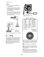
1. Drill a hole of 25 mm in diameter in the
mounting location.
2. Coat holder guide with silicone sealant,
and pass gasket, washer and locknut
onto holder guide in that order and then
tighten the locknut.
3. Set the sensor holder to the holder guide
from inside the boat. Tighten the locknut.
4. Launch the boat to check for water leak-
age around the sensor.
How to mount temperature sensor T-03MSB
4.9
Wiring
Connect the cable assy. (supplied) to the [12-
24 VDC/NMEA] port, and the transducer ca-
ble to the [XDR] port. Refer to the intercon-
nection diagram to connect cables. Leave
slack in cables to facilitate checking and
maintenance. See the next page for how to
ground the display unit.
Cable assy. signal names
Note 1:
Attach the MJ cable cap (supplied) to
the transducer cable to protect the connector
when the display unit is removed from the
boat.
Note 2:
Cut unused cores and tape them.
Note 3:
Connector of cable edge breaks eas-
ily. Be careful when connecting or disconnect-
ing the connector.
Note 4:
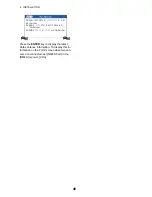
The fuse holder contains a spring
which fixes the fuse. To prevent detachment
of the spring, which would cause loss of pow-
er, tie the lines as shown on the next page.
Holder Guide
Sensor Holder
Locknut
Locknut
Washer
Gasket
φ
25 mm
Coat with
sealant.
Plate thickness
within 25 mm
Connector
Color
Remarks
1
TD-A
WHT
IEC61162-1/
NMEA0183
2
TD-B
BLU
3
RD-A
YEL
IEC61162-1/
NMEA0183
4
RD-B
GRN
5
12V-P(+)
BRN
Power output
(12 VDC)
6
12V-M(-)
ORG
7
DC-P-IN (+) RED
Power input
12-24 VDC
8
DC-M-IN (-) BLK
9
NC
–
10
SHIELD
–
Drain wire (to
GND terminal
on switchboard)
Transducer
cable
Ground
Switchboard, ground terminal,
external equipment
Cable assy.
(KON-004-02M, 2 m)
Transducer
1
2
3
4
5
6
7
8
9
10
Содержание FCV-627
Страница 1: ...FISH FINDER FCV 627 OPERATOR S MANUAL www furuno com B R I L L GAIN ...
Страница 62: ...D 1 ...
Страница 63: ...D 2 ...


