background image

4. MAINTENANCE & TROUBLESHOOTING 


4-4 

4.4 Diagnostics 

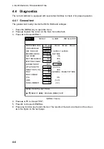
The current indicator is equipped with several test facilities to check it for proper operation. 
 

4.4.1 General 

test 

The general test mainly checks the ROM, RAM and voltages. 
 
1.  Press the [MENU] key to open the menu. 
2. Press 

 to place the cursor on the main menu title field. 

3. Press 

 to choose MENU 1. 

SHIP SPEED AVG :        15 sec

     30 sec    60 sec

90 sec

TIDE AVERAGE

:         2 min

REF TIDE DIFF

:    LAYER 1

  LAYER 2  LAYER 3

BEARING MODE :   32 CMPS    360 TRUE

NAV MODE

:           OFF

           ON

BOTTOM SEARCH:            NO

         YES

BTM TIDE TRACK :           OFF

           ON

ALM/KEY BEEP

:           OFF

           ON

WT SPD DEPTH

:            2 m      (2-400m)

RESET TRIP LOG :             NO

         YES

TEST

:             NO    GENERAL  PANEL PATTERN

ECHO RANGE

:        150 m   

TVG

:          OFF

          ON

GAIN

:               5           (1-40)

PANEL DIMMER

:               5           (0-7)

MENU ON INITIAL SETTINGS.

[

p

/

q

]:SELECT, [

t

/

u

]: CHANGE, [MENU]: EXIT

MENU 1

             MENU 2


ALARM           INSTALLATION            


MENU 1 menu 

4. Press 

 or 

 to choose TEST. 

5. Press 

 to choose GENERAL.   

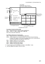
6.  Press any function key to start the test. The results of the test are shown on the screen 

as in the figure on the next page.     

Содержание CI-68

Страница 1: ...DOPPLER SONAR CURRENT INDICATOR CI 68 ...

Страница 2: ... 4200 FIRST EDITION FIRST EDITION OCT OCT 2003 2003 Printed in Japan Printed in Japan All rights reserved All rights reserved A1 A1 NOV NOV 27 2003 27 2003 PUB No PUB No OME 72520 OME 72520 00014802200 00014802200 00014802200 00014802200 DAMI DAMI CI 68 CI 68 0 0 0 1 4 8 0 2 2 0 0 0 0 0 1 4 8 0 2 2 0 0 OME72520A10 OME72520A10 OME72520A10 OME72520A10 O M E 7 2 5 2 0 A 1 0 O M E 7 2 5 2 0 A 1 0 ...

Страница 3: ...mediately turn off the power at the switchboard if the equipment is emitting smoke or fire Continued use of the equipment can cause fatal damage to the equipment Contact a FURUNO agent for service Make sure no rain or water splash leaks into the equipment Fire or electrical shock can result if water leaks in the equipment ELECTRICAL SHOCK HAZARD Do not open the equipment Only qualified personnel s...

Страница 4: ...l Turn off the equipment at the switchboard if it becomes warm or is making strange noises Contact your dealer at your earliest convenience A warning label is attached to the transceiver and monitor units Do not remove the labels If a label is missing or damaged contact a FURUNO agent or dealer about replacement WARNING To avoid electrical shock do not remove cover No user serviceable parts inside...

Страница 5: ...RPRETING THE DISPLAYS 2 1 2 1 Tide Vector Display 2 1 2 2 Ship s Speed Display 2 5 2 3 Graph Display 2 7 2 4 Course Plot Display 2 9 2 5 Echo Level Display 2 10 2 6 Error Display 2 11 3 CUSTOMIZING THE SYSTEM 3 1 3 1 Menu Operation 3 1 3 2 Function Keys 3 3 3 2 1 Programming the function keys 3 3 3 2 2 Using the function keys 3 3 3 3 MENU 1 Menu 3 4 3 4 MENU 2 Menu 3 7 3 4 1 MODE menu 3 7 3 4 2 DI...

Страница 6: ...g Fuses 4 2 4 3 Troubleshooting 4 3 4 4 Diagnostics 4 4 4 4 1 General test 4 4 4 4 2 Panel test 4 6 4 4 3 Test pattern 4 7 4 5 Error Messages and Alerts 4 8 APPENDIX AP 1 MENU TREE AP 1 TIDE MEASUREMENT IN NAV MODE AP 3 PRINCIPLE OF OPERATION AP 6 SPECIFICATIONS SP 1 INDEX IN 1 ...

Страница 7: ...n or speed data from a GPS navigator and heading data from a gyrocompass or satellite compass Single mold transducer plus compact monitor unit control unit transceiver unit and junction box option permit installation on small vessels Data is displayed on a bright non fading 10 4 TFT LCD Background color is selectable from three colors Commercially available monitor may be used in lieu of the LCD m...

Страница 8: ...DC AC INVERTER TR 2451 24 VDC Standard Supply Optional Supply Local Supply CONTROL UNIT CI 6888 VGA Monitor OR NMEA1 Output NMEA1 Input NMEA2 CIF Output NMEA2 CIF Input Current Indicator Data AUX NMEA CIF Current Indicator Data Data for Display Heading Sensor Alert Alarm Speed Log 2 lines KP Output KP Input Two lines Power ON OFF Status Contact signal System configuration ...

Страница 9: ...vii DISPLAY EXAMPLE Object and color Tide of layer 1 Yellow Tide of layer 2 Purple Tide of layer 3 Light blue Own ship speed vector Green Heading line White dashed Tide vector display ...

Страница 10: ......
Страница 11: ...R1 LYR3 Set tide measuring depths for respective layers Setting Knob Sets measuring depth and range RANGE Sets range The range which can be set depends on mode TRACK MODE Chooses tracking mode among ground water or nav and auto DISP MODE Chooses a display mode BRILL Adjusts brilliance of LCD MENU Opens and closes the menu CursorPad Chooses menu items and options Increases or decreases numerical se...

Страница 12: ...m Version No CI 68 CI 6888 VOL 6651000 XX XX MEM 1 2 3 OK CI 6810 VOL 6651001 XX XX TBL MEM 1 2 3 4 5 6 7 8 OK ANA 12V 12 03V BV 110 0V TRM 25 02 C DSW 00 00 00 00 DSW 00 00 00 Diagnostic test Note The example screens shown in this manual may not match the screens you see on your display The screen you see depends on your system configuration and equipment settings 2 To turn the power off press th...

Страница 13: ...g g g g g g c CURSOR PAD BRILL KEY CHANGE SETTING 6 L L Brilliance adjustment window Note Execute the next step within five seconds after displaying the brilliance adjustment window Otherwise the window is erased 2 Press or to raise the brilliance or to lower it The brilliance may also be adjusted by pressing the BRILL key In this case brilliance is adjusted cyclically 0 1 7 6 0 Note You can adjus...

Страница 14: ...vector display The tide vector display mainly shows tide speed and direction for three layers with a vector Tracking Mode Tide Speed Range Echo Level Heading Water Temperature Water Temperature Graph Sensor required Tide of Layer 1 Yellow Tide of Layer 2 Purple Tide of Layer 3 Light blue Own Ship Vector Green Tide Differential Tide Speed and Direction 3 layers Speed Course Mode Marker Echo Display...

Страница 15: ...t Speed History Graph Port Starboard Speed History Graph Fore Aft Speed Port Starboard Speed Drift Angle Own Ship Vector Synthesized Speed Vector Green Ship s speed display 1 4 3 Graph display The graph display plots water temperature and depth data in graph form Sensor required Text Window Depth Graph Mode Marker Water Temp Graph Tide Graph or Tide Diff or Ship Speed Trip Distance Marker Graph di...

Страница 16: ...tion North Mark Tide Vector Ship s Track Own Ship Position Course plot display 1 4 5 Text display The text display provides various nav data in digital format Tracking Mode Heading Tide Speed and Direction 3 layers Speed and Course Mode Marker Tide Differential Water Temperature Sensor required Trip Distance Fore Aft Speed Port Starboard Speed Drift Angle Text display ...

Страница 17: ...e echo level display shows the strength of the echoes captured by three sounding beams Note that ECHO LEVEL in the MODE menu must be set to ON to show the echo level display Echo Level Tide Vector Beam 2 Beam 1 Beam 3 Echo Display Range Echo level display ...

Страница 18: ... or LYR3 key as appropriate to show the depth setting window SETTING DEPTH LAYER1 20m 2 400 KNOB OR CURSOR PAD CHANGE SETTING Depth setting window 2 Within five seconds after completing step 1 operate the Setting Knob or the CursorPad to set depth of measurement The setting range is 2 400 meters Setting Knob Rotate clockwise to raise the range counterclockwise to lower the range CursorPad Press or...

Страница 19: ...enu sub menu in the installation menu is set to EXTERNAL To choose the tracking mode press the TRACK MODE key The tracking mode changes according to the setting OFF or ON of NAV MODE in the MENU 1 menu The current tracking mode appears at the top left hand corner on the screen OFF The tracking mode changes cyclically in the sequence of ground tracking water tracking and auto ON The tracking mode c...

Страница 20: ... speed The ship s speed range setting window shown depends on whether SCALE SYNC in the DISP2 sub menu is set to ON or OFF ON Port starboard and fore aft speeds are synchronized The ship s speed range setting window appears Set speed appropriately OFF The ship s speed range setting window appears Set fore aft speed appropriately Graph The speed range setting window shown depends on the setting of ...

Страница 21: ...r wrong data is denoted with Tide Average Setting Tracking Mode Tide Speed Range Echo Level Heading Water Temperature Water Temperature Graph Sensor required Tide of Layer 1 Yellow Tide of Layer 2 Purple Own Ship Vector Green Speed Course Mode Marker Echo Display Range Heading Line Layer 1 Yellow Layer 2 Purple Layer 3 Light blue Speed and direction of tide and tide differential Tide of Layer 3 Bl...

Страница 22: ...ilability for last three minutes scrolling from right to left The color represents tracking mode as shown below Current mode 3 min Green Ground tracking mode Blue Water tracking mode nav mode Background Speed error Speed course Speed made good and true course are shown The displayable range is 0 0 to 40 0 kts for speed and 0 to 359 for course N Heading fed from heading sensor True course Speed mad...

Страница 23: ... movement of layer 3 relative to surface water Ship s movement relative to surface water Surface Layer Reference layer Ground Tracking Mode Water Tracking Mode Nav Mode Layer 1 Tide movement of layer 1 Layer 2 Layer 3 Tide movement of layer 2 Tide movement of layer 3 GPS Satellies Ship s movement measured by using satellites Based on ground Tide differential Tide speed and direction differential a...

Страница 24: ...ight bluePurple Light blue Purple Light blue Purple Yellow Reference Layer Left half Measuring Layer Right half Purple Yellow Purple Yellow Ship s speed vector The ship s speed vector may be shown on the vector display This vector can be turned on or off with SHIP SPD VCTR in the DISP1 menu Electronic bearing scale The electronic bearing scale shows bearing If a heading sensor is connected the sca...

Страница 25: ... s speed Ship s speed Water tracking layer selected Ground tracking speed Water tracking speed Fore aft speed Speed in the fore aft direction The speed setting range is 0 0 to 40 0 kt Fore speed is denoted with a yellow above the speed readout and aft speed with a yellow below the speed readout Port starboard speed Speed in the port starboard direction The speed setting range is 0 0 to 40 0 kt Por...

Страница 26: ...ge with HISTORY SHIFT in the DISP2 menu The latest 60 seconds of fore aft speed is shown scrolling from right to left across the screen Port starboard history graph This graph shows port starboard speed history over time which is useful in trawling DRIFT HISTORY in the DISP2 menu sets the maximum range for the graph The latest 60 seconds of port starboard speed is shown scrolling from top to botto...

Страница 27: ...w may be turned on or off with TEXT WINDOW in the DISP1 menu When the text window is turned off 12 hours of graph data are shown Tide or tide differential speed graph You may choose the type of graph to display with MODE in the DISP1 menu The maximum tide speed or ship s speed range may be chosen with TIDE RANGE in the DISP1 menu Tide direction or course may be chosen with TIDE GRAPH in the DISP1 ...

Страница 28: ...de Blue Water tracking mode nav mode Background Ship s speed error Depth graph The depth graph displays depth data in graph form If in the water tracking mode the depth is greater than the depth range no depth data is displayed To graph depth from an external source set DEPTH SOURCE in the OTHER menu sub menu in the installation menu to EXTERNAL Trip distance marker The trip distance marker shows ...

Страница 29: ...om the screen center and when own ship position reaches the edge of the screen it is brought back to the screen center You may turn the ship s track line on or off with SHIP TRACK in the DISP2 menu Tide vector The length of the tide vectors may be chosen with VECTOR LENGTH in the DISP2 menu Vectors may be turned on or off with LAYER 1 LAYER 3 in the DISP1 menu North mark The north mark points upwa...

Страница 30: ...Beam 3 Echo Display Range Echo level display Description of echo level display indications Item Description Echo level Echo status of beam 1 fore beam 2 starboard and beam 3 port is displayed in eight colors Echo display range The echo display range can be set with ECHO RANGE in the MENU 1 menu ...

Страница 31: ...error kt Tide vector speed graph and course plot displays Text and echo level displays 2 Ship s speed error 2 7 12 0 SPEED FORE AFT DRIFT ANGLE SPEED PORT STBD 13 GT SPEED kt 12 0 2 7 DRIFT kt DIR 13 2 Ship s speed error Ship s speed display Text display Speed and course error displays 1 No data is being input from the transceiver unit to the display unit If this occurs contact a FURUNO agent or d...

Страница 32: ...is abnormal 1 2 Tide vector speed graph and course plot displays Text and echo level displays kt Tide and tide differential error displays 3 Displayed when echo for a measuring layer is not present The readout for the offending measuring layer is not reliable 4 Displayed when the depth setting for a measuring layer is improper The readout for the offending measuring layer is not reliable Improper ...

Страница 33: ...eration 1 Press the MENU key to open the menu The last used menu appears TIDE VECTOR OFF ON SHIP SPEED OFF ON GRAPH OFF ON COURSE PLOT OFF ON TEXT OFF ON ECHO LEVEL OFF ON BACKGROUND CLR BLACK WHITE BLUE MENU ON DISPLAY SETTINGS p q SELECT t u CHANGE MENU EXIT MAIN menu title SUB menu title Help MENU 1 MENU 2 ALARM INSTALLATION MODE DISP1 DISP2 MODE menu 2 Press to place the cursor on the main men...

Страница 34: ...cked to prevent unintentional adjustment of its settings When you move the cursor from ALARM to INSTALLATION the following message appears To open the INSTALLATION menu press any function key PRESS ANY FUNC KEY TO OPEN INSTALLATION MENU PRESS MENU KEY TO OPEN ALARM MENU 4 Press or to choose menu item desired Selected item is displayed in reverse video and menu help appears in the box at the bottom...

Страница 35: ...CTED ITEM TO F KEY is displayed about five seconds Function key number pressed 5 Press the MENU key to close the menu 3 2 2 Using the function keys The function keys provide shortcut menu operation and they are not programmed at the factory If a function key contains no program when pressed the message NO FUNCTION ASSIGNED TO F KEY appears on the display for about five seconds function key pressed...

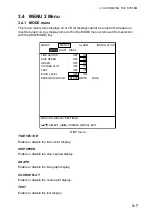
Страница 36: ... SELECT t u CHANGE MENU EXIT MENU 1 MENU 2 ALARM INSTALLATION MENU 1 menu SHIP SPEED AVG Choose the averaging time for the ship s speed display The choices are 15 30 60 and 90 seconds TIDE AVERAGE Choose the averaging time for the tide display If tide speed appears to be too slow choose a higher setting The choices are 15 s and 1 2 3 5 10 and 20 minutes REF TIDE DIFF Choose the reference layer for...

Страница 37: ... with the bottom depth to track on near bottom tide In this case the layer 3 indications shows BTTM instead of the tide measurement depth OFF Normal selection of measuring depth for layer 3 ALM KEY BEEP A key beeps to confirm correct key input input error or error message You may turn this beep on or off as desired The beep sounds when an alarm setting is violated regardless of whether this item i...

Страница 38: ...VG Turn echo TVG on or off GAIN Adjust echo level display color The higher the digit the nearer to the strongest color reddish brown GAIN does not adjust the gain of the received signal speed and tide values are not affected by this adjustment The setting range is 1 40 PANEL DIMMER Adjust the backlighting for the control panel from 0 7 ...

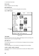
Страница 39: ...SHIP SPEED OFF ON GRAPH OFF ON COURSE PLOT OFF ON TEXT OFF ON ECHO LEVEL OFF ON BACKGROUND CLR BLACK WHITE BLUE MENU ON DISPLAY SETTINGS p q SELECT t u CHANGE MENU EXIT MENU 1 MENU 2 ALARM INSTALLATION MODE DISP1 DISP2 DISP menu TIDE VECTOR Enable or disable the tide vector display SHIP SPEED Enable or disable the ship s speed display GRAPH Enable or disable the tide graph display COURSE PLOT Enab...

Страница 40: ...F ON TEXT WINDOW OFF ON MENU ON DISPLAY SETTINGS p q SELECT t u CHANGE MENU EXIT MENU 1 MENU 2 ALARM INSTALLATION MODE DISP1 DISP2 Graph display settings DISP1 menu TIDE RANGE Set the tide range for the tide vector display graph display and echo level display The choices are 0 5 1 0 2 0 3 0 5 0 and 10 0 kts SHIP SPD VCTR Turn the ship s speed vector on or off on the tide vector display and echo le...

Страница 41: ...ing mode to use to display drift angle fore aft speed and port starboard speed on the ship s speed and text displays MODE Choose the item to show on the graph display among tide tide differential and ship s speed TIDE GRAPH Choose how to draw the tide on the graph display The choices are NORTH N E S W and SOUTH S W N E Normally use NORTH When the graph becomes difficult to read switch to SOUTH TEM...

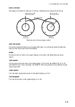
Страница 42: ...N MODE DISP1 DISP2 Tide vector display settings Ship s speed display settings Tide differential display settings DISP2 menu ECHO LEVEL Turn the echo level display on or off on the tide vector display DISP MODE Choose how to show the echo level display SOUNDER Echo strength shown in eight colors GRAPH Echo strength shown by graph COLOR GRADATION Color sounder AMPLITUDE GRAPH A scope Beam 3 Beam 1 B...

Страница 43: ...nu for it to become active DRIFT HISTORY Set the range for the port starboard speed history graph The choices are 0 5 1 and 2 kt HISTORY Set the range for the fore aft speed history graph The choices are 4 8 16 and 32 kt HISTORY SHIFT Set the amount of shift for the fore aft speed history graph among 2 1 0 1 2 4 and 8 kt SCALE Choose the scale to use in the course plot display from among 1 10000 1...

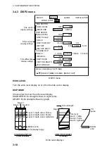
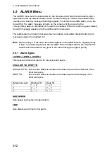
Страница 44: ...sabled independently Alarm messages appear in paragraph 4 5 Note Alarm priority is in the order the alarms appear on the ALARM menu highest priority is layer 1 and lowest priority is the trip alarm When multiple alarms are violated the audible and visual alarms are given to the alarm having the highest priority 3 5 1 Alarm types LAYER 1 LAYER 2 LAYER 3 Tide speed and direction alarms for respectiv...

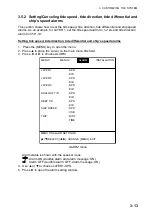
Страница 45: ...and ship s speed alarms 1 Press the MENU key to open the menu 2 Press to place the cursor on the main menu title field 3 Press or to choose ALARM LAYER 1 SPD DIR LAYER 2 SPD DIR LAYER 3 SPD DIR SHALLOW T D SPD DIR DEEP T D SPD DIR SHIP SPEED SPD CSE TRIP DIST TIME MENU ON ALARM SETTINGS p q SELECT t u CHANGE MENU EXIT MENU 1 MENU 2 ALARM INSTALLATION DISP2 ALARM menu Alarm status is shown with the...

Страница 46: ...decreased accordingly Your screen should now look something like the one shown below S E NE SE SW W NW 3 0kt DIR LAYER1 p q KEY MAX t uKEY MIN STATUS 0 0kt 0 TIDE MIN 1 0kt MAX 2 0kt QUIT ANY FUNC KEY DIRECTION MIN 0 MAX 0 N N Tide speed alarm setting Alarm setting screen tide speed set 7 Press any function key to return to the ALARM menu appears to the right of SPD 8 Press to choose DIR at LAYER ...

Страница 47: ... 5 3 Setting the trip alarm Trip distance alarm The trip distance alarm sounds when the vessel has traveled more than the preset distance 1 Press the MENU key to open the menu 2 Press to place the cursor on the main menu title field 3 Press or to choose ALARM 4 Press or to choose TRIP DIST 5 Press to show the trip distance setting screen TRIP ALARM t u KEY SET TRIP DIST 0 0 nm ANY FUNC KEY QUIT Di...

Страница 48: ...age appears 9 Press the MENU key to close the menu 3 5 4 Disabling enabling the audible alarm 1 Press the MENU key to open the menu 2 Press to place the cursor on the main menu title field 3 Press or to choose ALARM 4 Press or to choose the alarm you want to process An alarm where or appears 5 Press or to show or as appropriate 6 Press the MENU key to close the menu 3 5 5 Disabling an alarm 1 Pres...

Страница 49: ... within the rated voltage Cleaning Dust or dirt should be removed from exterior surfaces with a soft dry cloth For cleaning the LCD wipe it carefully to prevent scratching using tissue paper and an LCD cleaner To remove stubborn dirt use an LCD cleaner wiping slowly with tissue paper so as to dissolve the dirt Change paper frequently so the dirt will not scratch the LCD Do not use chemical based c...

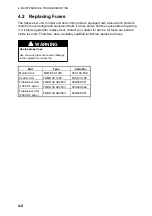
Страница 50: ...nt contact your dealer for advice All fuses are located inside the units Therefore have a suitably qualified technician replace the fuses WARNING Use the proper fuse Use of a wrong fuse can result in damage to the equipment or cause fire Unit Type Code No Monitor Unit FGMB 3A 125V 000 104 909 Control Unit FGMB 2A 125V 000 103 165 FGBO 3A AC250V 000 549 021 Transceiver Unit 100 VAC spec FGBO 5A AC2...

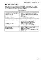
Страница 51: ...ve blown Request replacement of the fuse adjust brilliance ship s track is not displayed turn on SHIP TRACK in the DISP2 menu bottom echo is not shown on the echo level display check if the setting of ECHO RANGE in the MENU 1 menu is too low bottom is deeper than measuring range check setting of GAIN in the MENU1 menu echo display is interrupted suspect poor measuring conditions bottom is covered ...

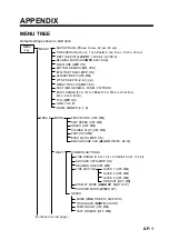
Страница 52: ...ec TIDE AVERAGE 2 min REF TIDE DIFF LAYER 1 LAYER 2 LAYER 3 BEARING MODE 32 CMPS 360 TRUE NAV MODE OFF ON BOTTOM SEARCH NO YES BTM TIDE TRACK OFF ON ALM KEY BEEP OFF ON WT SPD DEPTH 2 m 2 400m RESET TRIP LOG NO YES TEST NO GENERAL PANEL PATTERN ECHO RANGE 150 m TVG OFF ON GAIN 5 1 40 PANEL DIMMER 5 0 7 MENU ON INITIAL SETTINGS p q SELECT t u CHANGE MENU EXIT MENU 1 MENU 2 ALARM INSTALLATION MENU 1...

Страница 53: ...sults Description of control unit test results VOL Program version no of the OCK Board 66P3927 MEM Check of 1 ROM 2 SRAM and 3 EEPROM SIO OK if normal NG if abnormal Description of transceiver unit test results VOL Program version no of the PCP Board 66P3920 MEM Checks memory ICs on the PCP Board If all memory ICs are functioning properly OK appears NG No Good appears when an IC is abnormal and an...

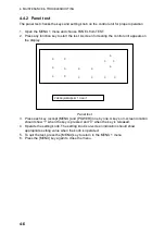
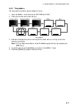
Страница 54: ...pears on the display 0 0 0 0 0 0 0 0 0 0 0 0 0 0 0 PRESS MENU KEY TO QUIT 0 Panel test 3 Press each key except MENU and POWER one by one A key s on screen location should show 1 when the key is pressed and 0 when the key is released 4 Operate the setting knob The setting knob s on screen indication should show appropriate setting value when the knob is operated 5 To quit the test press the MENU ke...

Страница 55: ...est Pattern Black Blue Green 16 tones of red 16 tones of green 16 tones of blue White Red Test pattern 3 Press to change the picture in the sequence shown above You may reverse the order by pressing Note You may adjust the brilliance of the FURUNO supplied monitor by operating the BRILL key 4 To quit the test press the MENU key to return to the MENU 1 menu 5 Press the MENU key again to close the m...

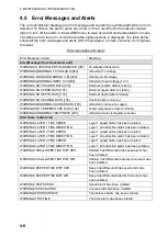
Страница 56: ...ition data is missing WARNING ABNORMAL COURSE DATA 105 Abnormal course error angle WARNING NO TEMPERATURE DATA 106 Water temperature data is missing WARNING ABNORMAL TEMP INPUT 201 Abnormal water temperature sensor Alert from control unit WARNING LAYER 1 TIDE SPEED Layer 1 speed alarm has been violated WARNING LAYER 1 TIDE DIRECTION Layer 1 tide direction alarm has been violated WARNING LAYER 2 TI...

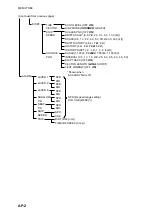
Страница 57: ...NGE 50 m 100 m 150 m 200 m 250 m 300 m 350 m 400 m 450 m 500 m TVG OFF ON GAIN 1 40 5 PANEL DIMMER 0 7 5 MENU 2 MODE TIDE VECTOR OFF ON SHIP SPEED OFF ON GRAPH OFF ON COURSE PLOT OFF ON TEXT OFF ON ECHO LEVEL OFF ON BACKGROUND CLR BLACK WHITE BLUE COMMON SETTINGS LAYER 1 OFF ON LAYER 2 OFF ON LAYER 3 OFF ON TIDE DIFF OFF ON Continued on next page MODE TIDE TIDE DIF SHIP SPD TIDE GRAPH NORTH SOUTH ...

Страница 58: ...TOR SHIP SPEED COURSE PLOT SCALE SYNC OFF ON DRIFT SCALE 0 5 1 0 2 0 3 0 5 0 10 0 kt SCALE 0 5 1 0 2 0 3 0 5 0 10 0 20 0 30 0 kt DRIFT HISTORY 0 5 kt 1 kt 2 kt HISTORY 4 kt 8 kt 16 kt 32 kt HISTORY SHIFT 2 1 0 1 2 4 8 kt SCALE 1 10000 1 20000 1 50000 1 100000 INTERVAL 0 5 1 0 1 5 2 0 2 5 3 0 3 5 4 0 4 5 5 0 SHIP TRACK OFF ON VECTOR LENGTH LONG SHORT TEXT WINDOW OFF ON DISP2 SPD 0 speed range setti...

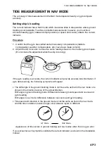
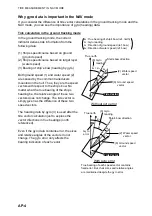
Страница 59: ... Do not make the adjustment while the ship is turning If the gyro reading is accurate the current indicator will provide accurate tide information If gyro data is wrong the following symptoms will appear The drift angle in the ground tracking mode is not the same as that in the nav mode or is shown in the direction reverse of the actual direction Drift angle in ground tracking mode Difference betw...

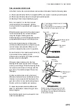
Страница 60: ... these two vectors does not change The tide vector is simply given as the difference of these two speed vectors The heading data by gyro 3 is used after the tide vector calculation just to express the vector directions in true bearings north referenced Even if the gyro data contains error the sizes and relative angles of the vectors do not change The gyro error only affects the bearing indication ...

Страница 61: ...e tide vector is calculated If the gyro data contains error the true bearing of the water speed vector changes rotates accordingly While the bearing of the nav speed vector does not change with the gyro error The relative angle of these two changes In other words the tide vector given as a difference between these two speed vectors changes in size speed and bearing by the gyro error Error in size ...

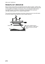
Страница 62: ...f the received signal is shifted from the transmitted frequency in proportion to the relative velocity between the vessel and underwater reflecting objects This is called the Doppler Effect This equipment calculates and displays movements of ship and currents at specific depths by measuring Doppler shifts obtained from three separate directions Plankton layer Bottom Frequency of reflected signal i...

Страница 63: ...floating base Navaid generated speed Ship s speed and course obtained by external navigation Absolute speed equipment GPS Fixed GPS satellites Navaid generated speed Pseudo ground tracking speed Water tracking speed Ground tracking speed Near surface layer Base of measurement Tide Tide is the movement of watermass at a particular depth To know absolute tide speed on ground the following two data a...

Страница 64: ...er B To calculate tide differential the following two data are used 1 Ship s speed and course based on layer A 2 Ship s speed and course based on layer B Tide differential between two layers is then given as a difference of these two speed vectors Tide Difference 1 2 Movement of layer B based on layer A Or 2 1 Movement of layer A based on layer B Layer B Base of measurement 2 Layer A 1 ...

Страница 65: ...ip End of trip Moving at 10 kt on ground Moving at 3 kt on ground 10 NM 1 hour trip 2 1 Assume that the ship and layer A are moving in the same direction and ship s speeds based on ground Vg and on layer A Vwa are measured as Vg 10 kt Ship s speed based on ground Vwa 7 kt Ship s speed based on layer A Speed of layer A based on ground C1 can be calculated as follows C1 Vg Vwa 10 7 3 kt ...

Страница 66: ...hip s speed based on layer A Vwb 5 kt Ship s speed based on layer B Tide differential calculations in ground tracking mode As an absolute ship s speed Vg is available in the ground tracking mode tide speeds of layer A C1 and layer B C2 based on ground are calculated as follows C1 Vg Vwa Speed of layer A based on ground C2 Vg Vwb Speed of layer B based on ground Thus the tide differential Cd betwee...

Страница 67: ...acking mode are not absolute but relative to this near surface layer Vw 9 kt Ship s speed based on near surface layer Vwa 8 kt Ship s speed based on layer A Vwb 5 kt Ship s speed based on layer B Base of measurement Layer A Start of trip End of trip 10 NM 1 hour trip Layer B 2 kt 5 kt Near surface layer 1 kt Assume that the ship and all measuring layers are moving in the same direction but at diff...

Страница 68: ...r A based on near surface layer D2 Vw Vwb Speed of layer B based on near surface layer The tide differential Dd between layers A and layer B is Dd D2 D1 Vw Vwb Vw Vwa Vwa Vwb 8 5 3 kt OR Tide differential based on layer B speed of layer A as viewed from layer B Dd D1 D2 Vw Vwa Vw Vwb Vwa Vwb 5 8 3 kt If you compare the results of calculations on this page with the ones on preceding pages you will ...

Страница 69: ... or 0 1 kt whichever is the larger 2 3 Direction All directions in one degree steps 360 2 4 Depth of measurement 3 300 m Actual depth depends on installation method and ground tracking mode underwater conditions 3 DISPLAY 3 1 Display VGA 640x480 dot Content Ship s speed course drift angle tide 3 layers tide differential 2 layers setting depth heading position echo level water temperature Displays ...

Страница 70: ...ata position data speed data current indicator data reverberation level data speed calibration data angle calibration data alarm output data other 7 POWER SUPPLY 7 1 Transceiver unit 100 110 115 120 200 220 220 230 240 VAC single phase monitor unit control unit 3A 100 VAC 1 5A 200 VAC 8 WATERPROOFING 8 1 Monitor unit IPX0 8 2 Transceiver unit IPX0 8 3 Control unit panel IPX2 8 4 Control unit rear ...

Страница 71: ...ISP2 menu 3 10 E Echo level display description 2 20 on off 3 8 overview 1 7 type 3 10 Echo range 3 6 Electronic bearing scale 2 14 Error display 2 21 Error messages 4 8 F Function keys 3 3 Fuse replacement 4 2 G Gain 3 6 General test 4 4 Graph display description 2 17 drawing method 3 9 mode 3 9 on off 3 7 overview 1 5 temperature display 3 9 Graph text 3 9 H Heading 2 12 Heading line 2 14 Headin...

Страница 72: ...3 9 Ship s speed vector on off 3 8 Ship s track on off 3 11 T Test pattern 4 7 Text display on off 3 7 overview 1 6 Tide averaging 3 4 Tide differential reference layer 3 4 Tide differential vector on off 3 8 Tide vector 2 14 interval 3 11 length 3 11 Tide vector display description 2 11 on off 3 7 overview 1 4 TRACK MODE key 1 9 Trip distance marker 2 18 Trip log resetting 3 5 Troubleshooting 4 3...

Отзывы: