Furuno CAN bus Network Design Guide
19
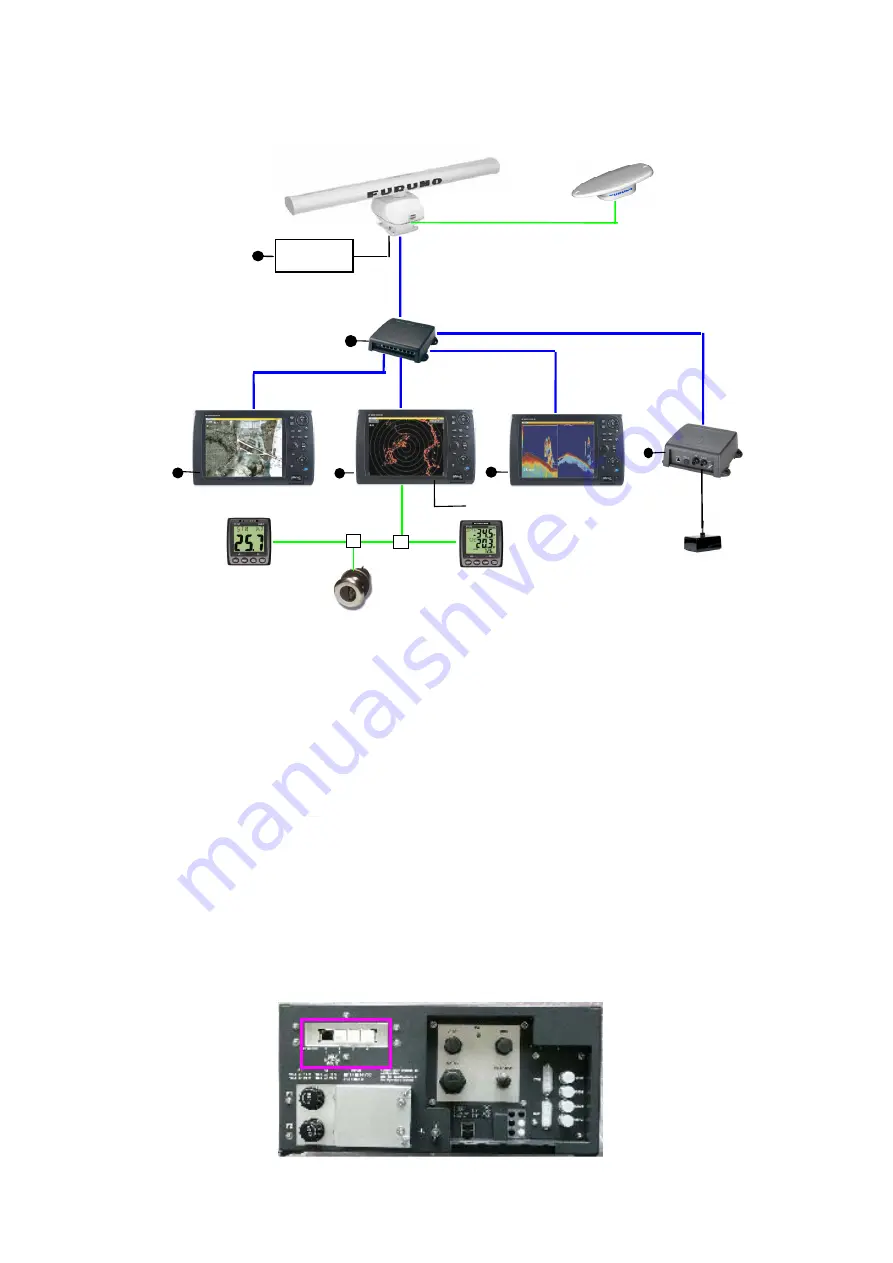
More complex networks are designed by using a network Hub, HUB-101 as shown in Fig.47.
Fig.47 Two or more MFD in network
The number of devices that can be connected to the network is;
DRS series: 2 units
HUB-101: 3
units
MFD8/12/BB: 10 units
RD-33:
3 units in CAN bus
The MFDBB has a built-in 4-port Hub, so up to two HUB-101’s are connected to the network
with a MFDBB.
The Ethernet ports 1 and 2 are designed to output power to the control units, DCU12 and
MCU-001. Do NOT connect MFD8/12 to ports 1 and 2, otherwise MFD8/12 in the earlier
production may be damaged. MFD8/12 in the current production has the protection circuit.
Fig.48 MFDBB, rear view
Smart Sensor, DST-800
SC-30
DRS
DFF-1/3
PSU-012
HUB-101
MFD
MFD
MFD
CAN bus (1)
Ethernet
12-24 Vdc
T-connector
Instrument, FI-50 series
CAN bus (2)
12 Vdc for CAN bus
See Fig.49.


