Furuno 00-167-964 Скачать руководство пользователя страница 12

Furuno CAN bus Network Design Guide


12

RD-33 

NMEA0183

NMEA0183

NMEA0183 

MFD 

NMEA0183 

(MAX. 3 units) 

NMEA-CAN bus 
Interface unit 
IF-NMEA2K1 

Device

Power supply 

A diode and a polyswitch (SMDC110F) on CONT2 board in the MFD unit protect the interface 
circuit against over-current and short-circuit.    See Fig.33. 


J3 DATA2                                        

J702              

J501                   J4 NMEA2000


NET_S_IN >17>                                  

>1> 

>1> 


>2> NET_S 

NET_C_IN >18>   


>2>


>2>   >3> 

NET_C 


    >3> >3> 


 >4> 

NET_H 


>5> NET_L 


Fig.33 Protection of network power circuit in MFD 


The maximum length of the network backbone is 150 m when the heavy cable is used and 50 
m when the light cable is used. More details are explained in the “CAN bus Network 
limitations” section. 


1.8 Network Grounding 

The network is grounded at a SINGLE location. This is normally done at the power supply 
connection to the network and should be well connected to the vessel’s grounding system. 
There must be no other ground connections on the network to avoid the problem of ground 
loops, which can harm the network performance. 


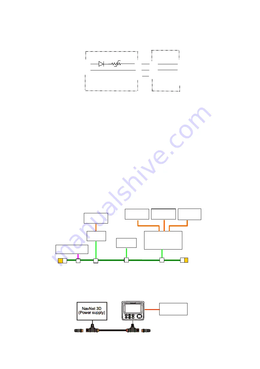
1.9 Connecting NMEA 0183 Device 

An NMEA 0183 device is connected to the CAN bus network via MFD unit or by using 
NMEA2000 Interface unit, IF-NMEA2K1. 


Fig.34 (a) Connection of NMEA0183 to CAN bus network   

with MFD and IF-NMEA2K1 


The remote display RD-33 is also capable of converting the NMEA0183 signal to the CAN 
bus signal.   


Fig.34 (b) Connection of NMEA0183 to CAN bus network with RD-33 

CONT1 

CONT2 

1.1A 

NMEA0183

Terminator

Terminator 

Содержание 00-167-964

Страница 1: ...ere developed to function in electrically noisy environments NMEA 2000 vs NMEA 0183 NMEA 2000 is a serial data network operating at 250k bps and NMEA 0183 is a serial data interface operating at 4 8k...

Страница 2: ...er supply or battery connections are made to the network backbone cable either directly or by means of a dedicated cable Some Furuno CAN bus devices can power the network through the network connector...

Страница 3: ...connecting segments of backbone cable together b For connecting terminations at the two ends of the cable c For connecting the network power source and d For connecting devices Two types of the conne...

Страница 4: ...trip Improper connection 1 3 Network Cable Two types of cable are used in the network heavy cable and light cable The selection of cable type for various portions including the drop cable of the netwo...

Страница 5: ...Power Red 22AWG 2 NET C Power Black 22AWG 3 NET H Signal White 24AWG 4 NET L Signal Blue 24AWG 5 1 4 Network Connector Furuno CAN bus network uses NMEA2000 standard 5 pin connectors for the network c...

Страница 6: ...F 020 000 167 963 Male and Female CAN bus light cable 6 m M12 05BM 05BF 060 00 167 964 Male and Female CAN bus light cable 1 m M12 05BFFM 010 000 167 965 Female CAN bus light cable 2 m M12 05BFFM 020...

Страница 7: ...le with the following part numbers The terminator should be attached at each end of the backbone cable The terminator has a 120 ohm resistor across pins 4 and 5 Parts Name Type Code Number Remarks Mal...

Страница 8: ...e the cable length between the T connector and the device can be extended more than 6 m Fig 24 Using internal terminator at both ends of backbone cable To activate the internal terminator a DRS The re...

Страница 9: ...en pins 4 and 5 1 Drain 2 RED 3 BLK 4 WHT 120 ohm resistor 5 BLU 6 7 8 PPL 9 YEL 10 GRN Fig 28 Termination on SC 30 e FI 50 The terminal resistor is on and off through Setup2 menu To show setup2 menu...

Страница 10: ...to the network is not necessary when the DRS is in the network The power connection is at either the end or middle of the network Note that the pin assignment of the network port differs between radom...

Страница 11: ...n line fuse and switch See Figs 31 and 32 The output voltage of the power supply is ideally 15 Vdc 5 ripple 0 25 Vp p or less as NMEA2000 standard considering input line variation and DC drop in the n...

Страница 12: ...the CAN bus Network limitations section 1 8 Network Grounding The network is grounded at a SINGLE location This is normally done at the power supply connection to the network and should be well connec...

Страница 13: ...ice taking 51 mA from the network power bus is a Two LEN device A LEN of 4 means that the device consumes up to 4 x 50 mA 200 mA Table 6 shows the LEN of Furuno CAN bus devices Table 6 LEN of Furuno C...

Страница 14: ...the total LEN of devices attached to the cable A is 75 the maximum length of cable A is 50 m from Table 7 Do the same for B The total length of cables A and B is less than 150 m Fig 38 Middle powered...

Страница 15: ...74 50 100 40 126 30 23 150 49 80 75 50 101 40 127 30 24 150 50 80 76 50 102 35 128 30 25 150 51 70 77 50 103 35 129 30 26 150 52 70 78 50 104 35 130 30 27 140 53 70 79 50 105 35 131 30 28 140 54 70 80...

Страница 16: ...re are a few things to consider 1 Voltage drop between the power source and the device located farthest from the power source is 3 0 Vdc or less when 12 Vdc battery is used 2 Total network load must b...

Страница 17: ...R2 is set to ON position 3 When two backbone cables are connected R1 and R2 are set to OFF position Fig 42 Internal terminators in FI 5002 The FI 5002 is added anywhere along the network backbone A ma...

Страница 18: ...dge Two or more CAN bus networks can be connected by using MFD and DRS via Ethernet as shown in Fig 46 All devices share the sensor data in the network The connection of the DRS having a CAN bus netwo...

Страница 19: ...4 port Hub so up to two HUB 101 s are connected to the network with a MFDBB The Ethernet ports 1 and 2 are designed to output power to the control units DCU12 and MCU 001 Do NOT connect MFD8 12 to por...

Страница 20: ...SW_P SW_P 5 SW_N SW_N 6 E_RD_N E_RD_N 7 PWR_SW_N N C 8 PWR_SW_P N C Power Synchronization Power on off synchronization amongst all of the NavNet 3D display units can be achieved when the dedicated Et...

Отзывы: