Furman P-240 IT Скачать руководство пользователя страница 6

6

P-2400 IT OWNER’S MANUAL

small magnetic field. Therefore, we recommend that it not be positioned adjacent to sensitive, low level signal processors, especially 
mic preamps, mixers, tape recorders, etc. Power amps may be more suitable “rack neighbors.”

The maximum benefit derived from balanced power is when it powers ALL equipment in an installation. Therefore, try to position 
the P-2400 IT in a central location so its power can be easily distributed everywhere it’s needed. If the total power consumption of 
all equipment exceeds 20 amps at 120 volts, delete high level or mechanical devices first (such as power amps, motors). If possible, 
physically isolate any equipment that has to be powered with conventional power through a different circuit, and route AC cords away 
from all other cabling. The balanced power produced by the P-2400 IT is restricted to use with electronic equipment only. Balanced 
power may not be used for lighting equipment, and access must be limited to use by qualified personnel only.
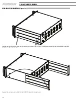
Rear Rack Mounting:

If you are installing the P-2400 IT in a rack that has rear as well as front mounting rails, you may easily secure it to the rear of your rack.  
Simply remove the securing screws from the side and front portions of the P-2400 IT’s adjustable rear rack ear and reinforcement side 
plate (located on either chassis side), reverse it and re-attach to the P-2400 IT chassis.  (See Figure 1.a, page 12)

OPERATION

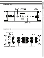
Switchable Voltage and True RMS Current Meter:   

Furman’s laboratory precision AC digital voltmeter continually measures incoming voltages within a typical tolerance of +/-1.5VAC.  It 
should be noted that the voltage reading is incoming.  

Furman’s laboratory precision True RMS digital current meter continually measures the total circuit AC load within a typical tolerance 
of +/- 0.5 amp.  Because these meters feature true RMS technology, the current readings are accurate regardless of load conditions 
(capacitive, inductive, or resistive). To switch between voltage and current, press the button labeled “Line Voltage/Current”. Hold this 
button down for two seconds to dim the brightness of the display.

Voltage Range Indicator:

This indicator is located in the lower left corner of the digital volt / amp meter lens assembly.  When AC voltage is within 5 volts (+/-) 
of a nominal 120VAC source, this tri-color indicator will be green (optimal).  However, if the voltage is between 110 to 114VAC, or be-
tween 126 to 130VAC, the indicator will turn amber (caution - not optimal).  If the incoming voltage is in an extreme range (below 110 
or above 130), the indicator will turn red.  This range is far from optimal, and may be potentially damaging to some equipment.

Ground Fault Interrupter (GFCI):

The Ground Fault Circuit Interrupter (GFCI)  on the P-2400 IT’s rear panel is a special kind of circuit breaker that detects an imbalance 
in the current flowing into the two hot legs. The “missing” current is presumed to be flowing through the ground conductor (the round 
pin on an AC outlet).

Ground current often indicates a dangerous partial or full short circuit. If an imbalance is detected, the GFCI trips and cuts off power 
not only to itself, but to all the P-2400 IT outlets. If this occurs, the button on the GFCI marked “R” (Reset) will pop out. To restore 
operation, correct the fault and push the button in. You may test the proper operation of the GFCI at any time by simulating a ground 
fault by pushing the button marked “T” (Test). If the GFCI is working properly, this will cause the “R” button to pop out and cut off 
power. You can restore operation after a test by pushing in the “R” button.

Ground Lift Switch:

Ground loops are fairly common in many installations because AC cords with safety grounds are rarely connected to a single low-resis-
tance bus bar. When there is a significant difference in voltage between a source component’s neutral and ground and a load compo-
nent’s neutral and ground, the buzz and hum associated with this type of ground current noise (or loop) may occur. Additionally, many 
AC noise contaminants may be present on the AC ground wire. For these reasons, Furman’s P-2400 IT contains a Ground Lift Switch. 

This switch floats the output ground, eliminating ground noise and also, in many instances, the hum and buzz associated with ground 
loops. The P-2400 IT’s GFCI protection circuit assures that even when utilizing the power conditioner in this mode, operation is safe 
and secure. In fact, even if a connected component has a catastrophic failure, less than 5 milliamps current imbalance from line to 
ground or neutral to ground will instantly disconnect the voltage output from the P-2400 IT. This is far safer than any conventional 120 
VAC outlet and it has numerous noise reducing advantages. 

However, ground wiring in any studio, broadcast or club environment can be complex. Because all 14 outlets of the P-2400 IT are in 
parallel, it is still possible to have a ground loop if the two offending products are simultaneously connected to a single P-2400 IT. Use 
of multiple P-2400 IT’s may be necessary in extreme cases. Also, for studio and broadcast use, separating all digital processing products 
from all analog devices is highly recommended and can be accomplished by separating these components into the two isolated banks, 
or for the very best performance, using  two P-2400 IT’s.

Содержание P-240 IT

Страница 1: ......

Страница 2: ......

Страница 3: ...ALL CONTENT 2009 FURMAN ALL RIGHTS RESERVED PRINTED IN CHINA ENGLISH Page 4 FRAN AIS Page 14 ESPA OL Page 24 P 2400 IT OWNER S MANUAL P 2400 IT GUIDE DE L UTILISATEUR P 2400 IT MANUAL DEL PROPIETARIO...

Страница 4: ...cy extension spatial cues and fast transient attacks are inherently low in signal level Further when AC noise is induced into audio processors pre amplifiers microphones powered monitors computers and...

Страница 5: ...ondition of the cords and cables at the plugs and the point where they exit your Furman conditioner To prevent risk of fire or injury damaged cords and cables should be replaced immediately 6 Clean yo...

Страница 6: ...indicator will turn red This range is far from optimal and may be potentially damaging to some equipment Ground Fault Interrupter GFCI The Ground Fault Circuit Interrupter GFCI on the P 2400 IT s rear...

Страница 7: ...m and perhaps changing the AC source Protection OK Indicator Although the Furman SMP circuit assures virtually maintenance free protection from transient voltage spikes and surges nature has a way of...

Страница 8: ...ground leakage to one of the connected components Action Needed Depress the reset button on the rear panel s GFCI outlet If the button pops out immediately when the unit is ener gized there may be an...

Страница 9: ...against defects or damages arising from improper installation This warranty shall be cancelable by Furman at its sole discretion if the product is modified in any way without written authorization fr...

Страница 10: ...3 000 AMPS RESPONSE TIME 1 NANOSECOND MAXIMUM SURGE CURRENT 6 500 AMPS NOISE ATTENUATION TRANSVERSE MODE 10 DB 10KHZ 40 DB 100 KHZ 50 DB 500KHZ NOISE ATTENUATION COMMON MODE 80 DB 20 KHZ 40 DB 20 KHZ...

Страница 11: ...outlet bank b convenience outlets voltage meter dimmer and current selector hold to select brightness master power switch digital led voltmeter ammeter and status indicators usb charger isolated ac o...

Страница 12: ...Figure 1 a Remove the securing screws from the side and front portions of the P 2400 IT s adjustable rear rack ear and reinforcement side plate located on either chassis side Reverse the rack ears an...

Страница 13: ...13 FRAN AIS ENGLISH Espa ol NOTES...

Страница 14: ...te un signal de qualit studio ou un faible taux de bruit Pour comprendre les besoins incroyables d avoir une alimentation CA pure sans bruit il est important de remarquer que les quipe ments sophistiq...

Страница 15: ...entivement ce manuel avant l utilisation AVERTISSEMENT Afin de r duire les risques d lectrocution n exposez pas cet quipement la pluie ou l humidit Il y a l int rieur du bo tier des tensions lev es da...

Страница 16: ...aut niveau tels que les amplificateurs de puissance les moteurs Si possible isolez physiquement tout quipement qui doit tre aliment par une alimentation conventionnelle gr ce un circuit diff rent et m...

Страница 17: ...est encore possible d avoir une boucle de terre si deux produits en conflit sont connect s simultan ment un seul P 2400 IT L utilisation de plusieurs P 2400 IT peut tre n cessaire dans des cas extr me...

Страница 18: ...imp dance du ch ssis et du c ble de blindage la terre est toujours sup rieure z ro ohm le courant la terre qui circule partir des condensateurs d alimentation lectrique et partir de la mise en route d...

Страница 19: ...l que le produit vendu aux termes des pr sentes est certifi e sans d faut mat riel et de fabrica tion pendant une p riode de cinq ans partir de la date d achat Si le produit n est pas conforme cette g...

Страница 20: ...ES SURTENSIONS pic de 188 VCA 3000 A TEMPS DE R ACTION 1 nanoseconde COURANT MAXIMUM DE SURTENSION 6500 A ATT NUATION DU BRUIT MODE TRANSVERSAL 10 dB 10kHz 40 dB 100 KHz 50 dB 500kHz ATT NUATION DU BR...

Страница 21: ...tre ajuster s lecteur courant bouton maintenez le enfonc pour s lectionner la luminosit commutateur lectrique voltm tre amp rem tre num rique conduit chargeur usb banque B d isolement de sortie C A b...

Страница 22: ...ure 1 a Retirez simplement les vis de montage des parties avants et lat rales du b ti r glable l arri re du P 2400 IT et la plaque lat rale de renfort situ e d un c t ou de l autre du ch ssis Inversez...

Страница 23: ...23 FRAN AIS ENGLISH Espa ol REMARQUE...

Страница 24: ...aciones de producci n de videos o cualquier entorno que requi era una calidad de se al de estudio en relaci n con el ndice de ruido Para comprender la incre ble necesidad de potencia de CA completamen...

Страница 25: ...1 Lea y observe todas las instrucciones de seguridad y funcionamiento antes de instalar su acondicionador de energ a Furman Serie Prestige Conserve estas instrucciones para consultarlas en el futuro 2...

Страница 26: ...dor de corriente RMS real El volt metro digital de CA de Furman con precisi n de laboratorio mide los voltajes entrantes dentro de una tolerancia normal de 1 5 VCA Debe observarse que la lectura de vo...

Страница 27: ...icos de menor costo Si se excede la capacidad de corriente RMS de 20 amperios del P 2400 IT el interruptor tensionado a resorte cam biar inmediatamente a la posici n de apagado Deber volver a mover la...

Страница 28: ...no dos l neas de 60 V con polaridad opuesta derivadas a tierra conectada en la toma central cuya diferencia es de 120 V Este tipo de energ a cuando corre por una sala no induce zumbidos en el cableado...

Страница 29: ...defectos son de tal tipo o naturaleza que est n cubiertos por esta garant a Furman autorizar al com prador a devolver el producto a la oficina central de Furman Los reclamos de garant a DEBEN estar a...

Страница 30: ...E SUJECI N PARA PICOS 188 VCA m ximo a 3000 amperes TIEMPO DE RESPUESTA 1 nanosegundo SOBRECORRIENTE M XIMA 6500 AMPERES ATENUACI N DEL RUIDO MODO TRANSVERSAL 10 dB 10kHz 40 dB 100 KHz 50 dB 500kHz AT...

Страница 31: ...vicio atenuador de voltaje selector actual pulsar para seleccionar el brillo interruptor principal volt metro amper metro y digital dirigido cargador usb banco B aislados de los enchufes de ca banco A...

Страница 32: ...mente quite los tornillos de seguridad de las porciones frontal y lateral de la muesca del estante posterior ajustable y la placa lateral de refuerzo ubicados en cualquiera de los laterales del chasis...

Страница 33: ...33 FRAN AIS ENGLISH Espa ol NOTAS...

Страница 34: ...34 P 2400 IT OWNER S MANUAL NOTES...

Страница 35: ...35 FRAN AIS ENGLISH Espa ol NOTES...

Страница 36: ...1690 Corporate Circle Petaluma California USA 94954 Phone 877 486 4738 Fax 707 763 1310 www FurmanSound com P2400IT_RevA...

Отзывы: