24
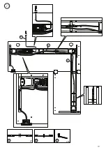
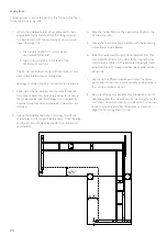
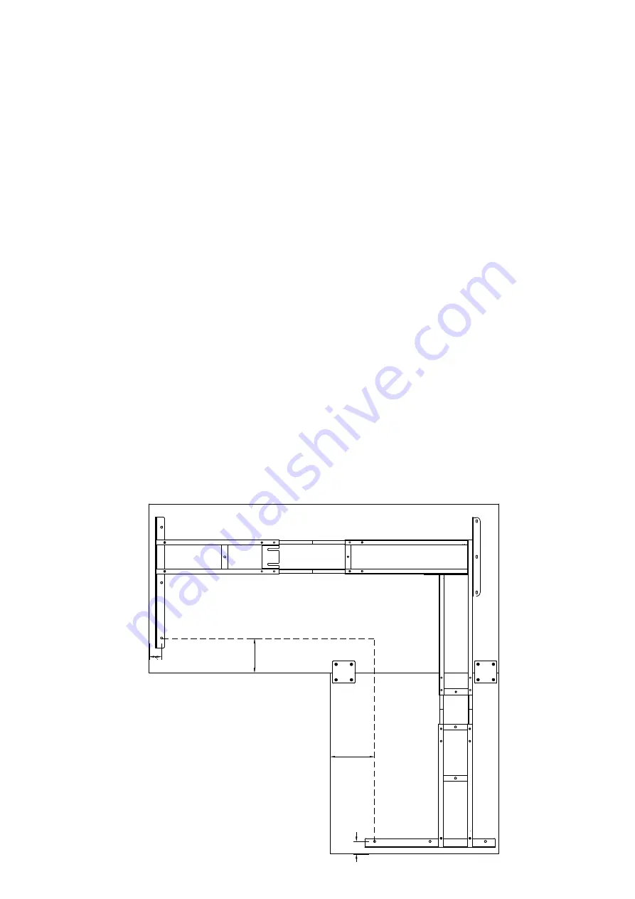
2”
6.75”
6.75”
2”
Laying it out
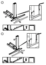
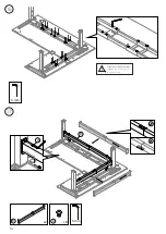
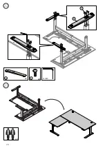
1. Attach the Side Brackets and Corner Bracket to their
appropriate Frame Ends (without the lifting columns).
It is best to start with the two Frame Ends you would
like on the larger top:
a. The Frame End (Part “I”) or Frame End
(w/Capture Plate), and
b. The Corner Assembly from Step 8 of the
Assembly Instructions.
The Corner Assembly will align with the corner of your
desk where the two tops come together.
See page 12 of the Assembly Instructions for reference.
2. Slide two of the Center Rails into the two Frame Ends
from Step 1 above. This assembly is easier to maneuver
than the entire frame and will allow you to see exactly
how the frame lines up and where all of the screws are
installed.
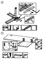
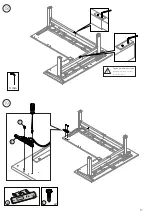
3. Line up the Side Bracket from 1-1 on page 10, with the
screw holes on the (larger) Side Bracket 2” from the edge,
and the front-most hole at least 6.75” from the front of
your desktop.
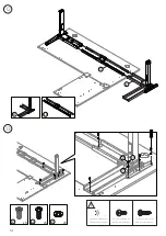
The easiest way to accurately position the Frame on the Top is
to use the Frame as a guide:
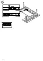
4. Slide the Center Rails into the open Frame End from the
Corner Assembly.
5. Create the final Frame End assembly with the remaining
Frame End and Side Bracket.
6. Slide this new assembly onto the Center Rails from Step
4, and position them as you did with the original Frame
End Assembly in Step 3. The example to the right shows
a desktop that is 27” deep on either side and 56” wide on
either side.
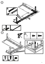
7. Use the tip of a Philips screwdriver to mark the center
point of each hole —this is more accurate and permanent
than using a marker or pencil.
8. Remove all frame components from the desktop - you’ll
need these later to assemble your frame. Using the marks
from step 7 drill pilot holes into your desktop. You’re now
ready to assemble and attach the frame as shown on
Pages “13-15” during Steps “10–15.”
Содержание Jarvis
Страница 2: ...Thank you for choosing a Jarvis desk from Fully ...
Страница 7: ...7 Not to scale Large Desktop Small Desktop AD AE Desktop Screw x16 Extra AF Desktop boxes 2 ...
Страница 9: ...9 J W C J x4 W C x1 3 2 W I C x4 W C x1 I 4 mm 4 mm ...
Страница 10: ...10 4 A V 2 A x2 V 2 4 mm B V 3 B x2 V 3 5 4 mm ...
Страница 11: ...11 6 K P W AB x2 W P K x2 AB 4 mm x2 U 6 L 7 U L 6 4 mm ...
Страница 12: ...12 x2 U 8 x2 AB U N AB 7 N 4 mm 9 Q x2 x8 T AE Q T 1 4 3 2 AD ...
Страница 17: ...17 19 18 3 mm T E E x2 T Tighten pre installed screws Skipping this step will result in stability issues ...
Страница 18: ...18 20 F F ...
Страница 19: ...19 21 G G H G x2 H x15 S ...
Страница 20: ...20 22 23 V D V x8 4 mm x2 D x2 ...
Страница 25: ...25 ...
Страница 26: ...version 40000492V C Everything you need to find your work flow ...

