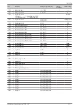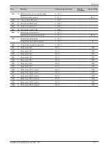
Line
Function
Setting range or display
Setting
increment
Basic setting
6800
S
History 1
Time, Date, Error code
6802
S
History 2
Time, Date, Error code
6804
S
History 3
Time, Date, Error code
6806
S
History 4
Time, Date, Error code
6808
S
History 5
Time, Date, Error code
6810
S
History 6
Time, Date, Error code
6812
S
History 7
Time, Date, Error code
6814
S
History 8
Time, Date, Error code
6816
S
History 9
Time, Date, Error code
6818
S
History 10
Time, Date, Error code
Service / Special operation
7070
S
HP interval
--, 1... 240
1 month
--
7071
S
HP time since maint
Reset ? (No, Yes)
0... 240
1 month
0
7072
S
Max starts compr1/hrs run
--, 0,1... 12
0,1
--
7073
S
Cur starts compr1/hrs run (since the 6 last weeks)
Reset ? (No, Yes)
0... 12
0
7076
S
Diff condens max/week
--, 1... 250
1
--
7077
S
Cur diff condens max/week
Reset ? (No, Yes)
0... 250
0
7078
S
Diff condens min/week
--, 1... 250
1
---
7079
S
Cur diff condens min/week
Reset ? (No, Yes)
0... 250
0
7090
S
DHW storage tank interval
--, 1... 240
1 month
---
7091
S
DHW stor tank since maint
Reset ? (No, Yes)
0... 240
0
7141
U
Emergency operation
Off, On
Off
Off : The heat pump does not use the boiler connection when a fault occurs (error 370)
On : The heat pump uses the boiler connection when a fault occurs (error 370).
In the "On" position, the energy costs can be onerous if the error is not eliminated.
7142
S
Emergency operating function type
Manual, Automatic
Manual
Manual : Emergency mode is not active when a fault occurs. (Emergency mode = OFF)
Automatic : Emergency mode is active when a fault occurs. (Emergency mode = ON)
In "Automatic" position, the energy cost can be onerous if the error is not detected and eliminated.
7150
I
Simulation outside temp
---, -50... 50 °C
0,5
--
7181
I
Phone no. responsibility 1
0... 255
7183
I
Phone no. responsibility 2
0... 255
Inputs / outputs test
7700
I
Relay test
No test
This consists of instructing the regulator's relays one by one and checking their outputs. This enables you to check
that the relays are working and that the cabling is correct. Check that each appliance in the installation is operating
correctly.
No test _ Everything is on STOP _ Relay output QX23, QX22, QX21 module 1 _ Relay output QX1 to QX6 _ Relay
output QX23, QX21, QX22 module 2 _ Relay output QX7.
The display shows the "Key" symbol. Pressing the Info button displays "Error 368".
Warning : The component being tested is receiving electrical power throughout the test
Installation and operating manual "1395 - EN"
Control Box
- 24 -

