background image

 SK-91465X-100PMC User Guide 

Chapter 5 Connectors 

UG-910056-11 

- 32 - 

© Fujitsu Microelectronics Europe GmbH 

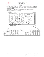
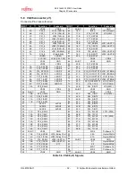
5.8  VG96 connector (J1) 

Connector-Pin cross-reference: 

MCU 

J1 

Function 

Evaboard 

MCU 

J1 

Function 

Evaboard 

VDD5 

VDD5 

51 

3A,B,C 

VSS5 

GND 

4A 

P23_0 

JP15 (CAN B) 

52 

16C 

INITX 

JP14 (Reset) 

4B 

P23_1 

JP16 (CAN B) 

53 

17A 

P16_7/ATGX 

JP9 (SW3) 

4C 

P31_0 

JP45 (TXD-A) 

54 

17B 

P17_2/PPG2 

5A 

P31_1 

JP46 (TXEN-A) 

55 

17C 

P17_3/PPG3 

5B 

P31_2 

JP48 (RXD-A) 

56 

18A 

P17_4/PPG4 

5C 

P31_3 

JP58 (TXD-B) 

57 

18B 

P18_0/SIN6 

JP21 (UART C) 

6A 

P31_4 

JP59 (TXEN-B) 

58 

18C 

P18_1/SOT6 

JP22 (UART C) 

6B 

P31_5 

JP62 (RXD-B) 

59 

19A 

P18_2/SCK6 

10 

6C 

P15_4 

JP51 (ERRN-B) 

60 

19B 

P18_4/SIN7 

JP38 (UART B) 

11 

7A 

P15_5 

JP66 (EN-B) 

61 

19C 

P18_5/SOT7 

JP39 (UART B) 

12 

VDD5R 

VDD5R 

62 

20A 

P18_6/SCK7 

13 

VCC18C 

JP40 (C50, C29) 

63 

VDD5 

VDD5 

14 

VSS5 

GND 

64 

3A,B,C 

VSS5 

GND 

15 

VDD5 

VDD5 

65 

20B 

P17_5/PPG5 

16 

7B 

P16_0/PPG8 

LED D3 

66 

20C 

P17_6/PPG6 

17 

7C 

P16_1/PPG9 

LED D4 

67 

21A 

P17_7/PPG7 

18 

8A 

P16_2/PPG10 

LED D5 

68 

21B 

P15_0/OCU0/TOT0  JP41 (STBN-A) 

19 

8B 

P16_3/PPG11 

LED D6 

69 

21C 

P15_1/OCU1/TOT1  JP47 (ERRN-A) 

20 

8C 

P27_0/AN16 

LED D7 

70 

22A 

P15_2/OCU2/TOT2 

JP61 (EN-A) 

21 

9A 

P27_1/AN17 

LED D8 

71 

22B 

P15_3/OCU3/TOT3  JP43 (STBN-B) 

22 

9B 

P27_2/AN18 

LED D9 

72 

22C 

P22_0/RX4/INT12 

JP 5 (CAN A) 

23 

9C 

P27_3/AN19 

LED D10 

73 

23A 

P22_1/TX4 

JP 8 (CAN A) 

24 

10A 

P28_0/AN8 

74 

23B 

P24_0/INT0 

JP4 (SW1) 

25 

VDD5 

VDD5 

75 

3A,B,C 

VSS5 

GND 

26 

3A,B,C 

VSS5 

GND 

76 

VDD5 

VDD5 

27 

10B 

P28_1/AN9 

77 

23C 

P24_1/INT1 

JP6 (SW2) 

28 

10C 

P28_2/AN10 

78 

24A 

P24_2/INT2 

29 

11A 

P28_3/AN11 

79 

24B 

P24_3/INT3 

30 

11B 

P28_4/AN12 

80 

24C 

P24_4/INT4 

31 

AVCC5 

AVCC5 

81 

25A 

P24_5/INT5 

32 

AVRH5 

AVRH5 

82 

25B 

P24_6/INT6 

33 

AVSS5 

AVSS5 

83 

25C 

P24_7/INT7 

34 

11C 

P29_0/AN0 

84 

26A 

P14_0/ICU0 

JP10 (SW4) 

35 

12A 

P29_1/AN1 

85 

26B 

P14_1/ICU1 

36 

12B 

P29_2/AN2 

86 

26C 

P14_2/ICU2 

JP12 (SW5) 

37 

12C 

P29_3/AN3 

87 

27A 

P14_3/ICU3 

38 

13A 

P29_4/AN4 

88 

27B 

P14_4/ICU4 

39 

13B 

P29_5/AN5 

89 

27C 

P14_5/ICU5 

40 

13C 

P29_6/AN6 

90 

28A 

P14_6/ICU6 

41 

14A 

P29_7/AN7 

91 

28B 

P14_7/ICU7 

42 

3A,B,C 

VSS5 

GND 

92 

MD0 

Pulldown 1k 

43 

14B 

P22_4/SDA0 

JP18 (Pullup 10k) 

93 

X0A 

Crystal 32kHz 

44 

14C 

P22_5/SCL0 

JP22 (Pullup 10k) 

94 

X1A 

Crystal 32kHz 

45 

15A 

P19_0/SIN4 

JP26 (UART A) 

95 

3A,B,C 

VSS5 

GND 

46 

15B 

P19_1/SOT4 

JP29 (UART A) 

96 

X1 

Crystal 4MHz 

47 

15C 

P19_2/SCK4 

X17 

97 

X0 

Crystal 4MHz 

48 

16A 

P17_0/PPG0 

98 

MD1 

Pulldown 1k 

49 

16B 

P17_1/PPG1 

99 

MD2 

Pulldown 1k 

50 

VDD5 

GND 

100 

3A,B,C 

VSS5 

GND 

Table 5-6: VG96 (J1) Signals 

Содержание SK-91465X-100PMC

Страница 1: ...Fujitsu Microelectronics Europe User Guide FMEMCU UG 910056 11 MB91F465XA EVALUATION BOARD SK 91465X 100PMC USER GUIDE ...

Страница 2: ...er Guide Revision History UG 910056 11 2 Fujitsu Microelectronics Europe GmbH Revision History Date Issue 2007 04 11 V1 0 MSt Initial version 2008 09 05 V1 1 MSc China RoHS regulation added This document contains 40 pages ...

Страница 3: ...date of receipt by the customer 2 Should a Product turn out to be defect Fujitsu Microelectronics Europe GmbH s entire liability and the customer s exclusive remedy shall be at Fujitsu Microelectronics Europe GmbH s sole discretion either return of the purchase price and the license fee or replacement of the Product or parts thereof if the Product is returned to Fujitsu Microelectronics Europe Gmb...

Страница 4: ... 1 3 5 RS 232 and LIN 7 1 3 6 I C 7 1 3 7 MCU Pins 8 1 3 8 User Buttons 8 1 3 9 User LEDs and optional LCD 8 1 3 10 Power Supply 8 2 INSTALLATION 9 2 1 Jumper Settings 10 2 2 Jumper Coordinates 12 3 JUMPERS AND SWITCHES 13 3 1 Operating Mode S1 13 3 2 Power supply 14 3 2 1 Power switching by FlexRay physical layer 15 3 3 Analogue Power Supply Voltage 16 3 4 UART A 17 3 5 UART B LIN A 17 3 6 UART C...

Страница 5: ...Power Connector X13 27 5 2 Edge connector X4 X5 27 5 3 UART LIN Connector X6 X8 X12 28 5 4 CAN Connector X1 X2 29 5 5 FlexRay Connector X3 X7 29 5 6 USER LEDs optional LC Display 30 5 7 In Circuit Programming Connector J4 31 5 8 VG96 connector J1 32 6 SILK PLOT OF THE BOARD 33 6 1 Silk plot Top side 33 6 2 Silk plot bottom side 34 7 RELATED PRODUCTS 35 8 APPENDIX 36 8 1 Tables 36 8 2 Figures 37 9 ...

Страница 6: ... the Socket Adapter Board EMA MB91F465X NLS 100M20 and the Adapter Board EMA MB91V460A 00x together with the MB91V460A 100 FlexRay extension board 12V unregulated external DC power supply 5V and 3 3V onboard voltage regulators Power LEDs for all supply voltages Onboard voltage supervisor monitors both supply voltages In Circuit serial Flash programming All resources available for evaluation All MC...

Страница 7: ...ers provides differential transmit and receive capability between FlexRay controller and FlexRay bus 1 3 4 CAN Bus Two high speed CAN transceivers TLE6250GV33 are available to connect all available on chip CAN controllers to 9 pin D Sub connectors X1 and X2 The transceivers provides differential transmit and receive capability between CAN controller and CAN bus 1 3 5 RS 232 and LIN RS 232 and LIN ...

Страница 8: ...SW7 issues a local wake up request to the Flexray physical layers AMS8221B One additional button is reserved as System Reset button to reset the MCU but it is possible to disconnect the RST port with JP14 1 3 9 User LEDs and optional LCD Eight user LEDs are connected via two pull down resistor networks to port P27_D0 P27_D3 and to port P16_D0 P16_D3 Parallel to the LEDs the connector J2 can be use...

Страница 9: ...gure 2 1 AC plug adapter and insert this adapter into the connection terminal on the AC DC adapter Figure 2 2 AC plug adapter selection Check the selected output DC voltage of the AC DC In Plug adapter at the voltage selection key It should be 12V Change the output voltage only in a powered down condition Figure 2 3 DC voltage selection Select the low voltage adapter suitable to the power connecto...

Страница 10: ...losed K6 JP9 SW3 ATGX Jumper 2 pin Closed G10 JP10 SW4 TIN0 Jumper 2 pin Closed G10 JP11 CAN B TXD CAN0 Solder JP 3 pin 1 2 J10 JP12 SW5 TIN2 Jumper 2 pin Closed G10 JP13 Reset immediate delayed Solder JP 3 pin 1 2 E7 JP14 RESET Jumper 2 pin Closed F9 F8 JP15 RX CAN B CAN0 Jumper 2 pin Closed K11 JP16 TX CAN A CAN4 Jumper 2 pin Closed K11 JP17 X3 Shield pin 5 FlexRay B Jumper 2 pin Open E15 JP18 S...

Страница 11: ...P53 C pin Solder JP 2 pin Closed G22 JP54 LIN B Master Mode Jumper 2 pin Open J12 K12 JP55 V_MCU Jumper 2 pin Closed H20 JP56 WAKE LIN transceiver LIN B Solder JP 3 pin 1 2 J12 JP57 LIN B enable Jumper 2 pin Open J12 JP58 TXD FlexRay B Jumper 2 pin Closed E16 JP59 TXEN FlexRay B Jumper 2 pin Closed E16 JP60 VBAT LIN B Jumper 2 pin Open H5 JP61 EN A Jumper 3 pin 1 2 E13 JP62 RXD FlexRay B Jumper 2p...

Страница 12: ... C D E F G H J K L M N 1 1 2 2 3 3 4 4 5 5 6 6 7 7 8 8 9 9 10 10 11 11 12 12 13 13 14 14 15 15 16 16 17 17 18 18 19 19 20 20 21 21 22 22 23 23 24 24 25 25 26 26 27 27 A B C D E F G H J K L M N Figure 2 5 Jumper Coordinates UART C LIN A UART6 UART B LIN B UART7 CAN A CAN4 FlexRay Channel A UART A UART4 FlexRay Channel B CAN B CAN0 ...

Страница 13: ...shown with a grey shaded area 3 1 Operating Mode S1 The DIP switch S1 is used to set the operating mode of the MCU Ensure that the mode pin settings correspond to the operation mode of the application For more detailed information please check the Hardware Manual of the microcontroller DIP switch Setting Logical value ON closed 1 high S1 1 MD0 OFF open 0 low ON closed 1 high S1 2 MD1 OFF open 0 lo...

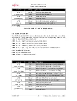
Страница 14: ... of whole board JP55 Connects the MCU Io voltage V_MCU to V_ALL Can be used for current measurement of MCU JP25 Selects the Gate input voltage of MOSFET Q2 Vin INHx JP40 Connects Vs Pin 1 of X8 to Vin JP60 Connects Vs Pin 1 of X12 to Vin JP1 Selects Vcc of CAN A Pin 3 of U2 5V or V_ALL JP11 Selects Vcc of CAN B Pin 3 of U4 5V or V_ALL Jumper Setting Description 1 2 MCU Peripherals 5V Vcc JP63 Vcc ...

Страница 15: ...al layer X9 X11 For this reason the Vcc voltage Selected by JP63 is controlled by a MOSFET Q2 12V level at the Gate pin will pass the Vcc voltage to the board Connecting 0V at the Gate pin the MOSFET Q2 switch off the Vcc power supply of the board JP25 selects if Vin 12V or the FlexRay physical layer INHx pins are connected to the Gate pin JP27 selects if INHx pin of FlexRay Physical layer channel...

Страница 16: ...c is disconnected from Vcc Closed AVRH is connected to AVcc JP3 AVRH Open AVRH defined by resistor network 1 Closed AVss is connected to GND JP7 AVss Open AVss is disconnected from GND Default grey Table 3 4 Jumper settings for Analogue Power supply 1 By default the resistor network R8 R11 is not mounted on the board By default the A D converter supply and reference voltage is same as the microcon...

Страница 17: ...ceiver U7 or one LIN transceiver U6 can be connected to one of the microcontroller s UART interfaces Connect to D Sub X8 corresponding RS232 or LIN cable By default RS232 is selected to X8 JP42 Selects if RS232 or LIN is connected to SIN7 of MCU JP44 Selects if RS232 or LIN is connected to SOT7 of MCU JP40 Selects if UARTB or LINA is connected to pin2 of X8 JP49 Some programs e g Terminals need a ...

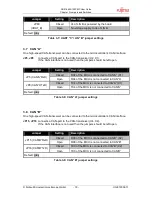
Страница 18: ...ected to SIN6 of MCU JP68 Selects if RS232 or LIN is connected to SOT6 of MCU JP65 Selects if UARTC or LINB is connected to pin2 of X12 JP69 Some programs e g Terminals need a connection between CTS and RTS JP57 Enable LIN Transceiver JP54 Selects LIN Master mode JP60 Connects Vs Pin 1 of X12 to Vin Jumper Setting Description 1 2 SIN6 of the MCU is connected to U10 RS232 JP67 UART C LIN B 2 3 SIN6...

Страница 19: ...MCU is connected to CAN A X1 JP5 CAN A RxD Open RX4 of the MCU is not connected to CAN A Closed TX4 of the MCU is connected to CAN A X1 JP8 CAN A TxD Open TX4 of the MCU is not connected to CAN A Default grey Table 3 8 CAN A jumper settings 3 8 CAN B One high speed CAN transceiver can be connected to the microcontroller s CAN interface JP15 JP16 connects a CAN port to the CAN transceiver U4 X2 If ...

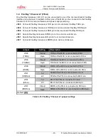
Страница 20: ...n to Vio or microcontroller pin JP61 Selects FlexRay transceiver EN pin to Vio or microcontroller pin JP47 Connects FlexRay transceiver ERRN pin to microcontroller pin Jumper Setting Description Closed TXDA of the MCU is connected to FR A JP45 TXDA Open TXDA of the MCU is not connected to FR A Closed TXENA of the MCU is connected to FR A JP46 TXENA Open TXENA of the MCU is not connected to FR A Cl...

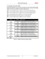
Страница 21: ...in to Vio or microcontroller pin JP66 Selects FlexRay transceiver EN pin to Vio or microcontroller pin JP51 Connects FlexRay transceiver ERRN pin to microcontroller pin Jumper Setting Description Closed TXDB of the MCU is connected to FR B JP58 TXDB Open TXDB of the MCU is not connected to FR B Closed TXENB of the MCU is connected to FR B JP59 TXENB Open TXENB of the MCU is not connected to FR B C...

Страница 22: ...ated In this case only the internal reset is active e g power on JP33 The signal on the DTR RTS line can be negated with this jumper Remove the jumper in order to disable the RS232 reset circuit Jumper Setting Description 1 2 DTR of UART A is selected JP28 DTR RTS A 2 3 RTS of UART A is selected 1 2 DTR of UART B is selected JP50 DTR RTS B 2 3 RTS of UART B is selected 1 2 DTR of UART C is selecte...

Страница 23: ...U is connected to SW3 JP9 SW3 Open No connection to the microcontroller Closed Pin 2 ICU0 TIN0 of the MCU is connected to SW4 JP10 SW4 Open No connection to the microcontroller Closed Pin 4 ICU2 TIN2 of the MCU is connected to SW5 JP12 SW5 Open No connection to the microcontroller Closed INITX is connected to the reset IC and SW6 JP14 Reset Open No connection to INITX 1 2 WAKE of FlexRay Transceiv...

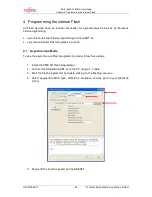
Страница 24: ...s serial Flash programming via X6 UART A synchronous serial Flash programming via J4 4 1 Asynchronous Mode To use the asynchronous Flash programming mode follow these steps 1 Install the FME FR Flash programmer 2 Connect the Starterkit UART A to the PC using a 1 1 cable 3 Start the Flash programmer by double clicking on the flashprg exe icon 4 Select appropriate MCU type COM Port baudrate and the ...

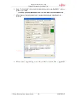
Страница 25: ... Press the Automatic button to start programming and release the RESET button or power up the board CAUTION DO NOT INTERRUPT OR CUT OFF POWER DURING ERASE 7 When download and programming is completed successfully following screen appears 8 After successful programming reset or Power off on the board to start the application ...

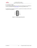
Страница 26: ...e Flash ROM synchronously special third party soft and hardware has to be used e g GALEP 4 from www conitec de This tool is not available for free A dedicated Flash programming socket J4 is provided on the evaluation board for direct connection to this programmer Figure 4 1 J4 Flash programming socket n c 1 MD0 3 RST 5 SOT4 7 VCC 9 2 n c 4 MD2 6 SIN4 8 SCK4 10 GND ...

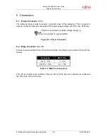
Страница 27: ... power supply voltage 12V DC max 2600mA Figure 5 1 Power Connector 5 2 Edge connector X4 X5 All pins except oscillator Pins of the microcontroller are directly connected to X4 and X5 as follows Connector MCU Pins X4 1 50 1 50 X25 51 100 51 100 Table 5 1 MCU Pin Connectors The odd pin numbers are located on the one side and the even pin numbers are located on the other side of the connector Shield ...

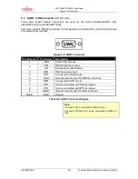
Страница 28: ... Figure 5 2 UART Connector Pin Number Pin Signal Description 1 VBat Power from LIN bus TXD RS 232 transmit output 2 LIN Bi directional LIN interface 3 RXD RS 232 receive input 4 DTR Connected to DSR pin 6 5 GND Ground normally used for RS232 connection 6 DSR Connected to DTR pin 4 7 RTS Can be connected with CTS by jumper 8 CTS Can be connected with RTS by jumper 9 LGND Ground normally used for LI...

Страница 29: ... Not used 7 CANH HIGH level CAN voltage input output 8 NC Not used 9 NC Not used Shield GND Ground Table 5 3 CAN Connector Signals 5 5 FlexRay Connector X3 X7 Two 9 pin D Sub male connectors are used for the two FlexRay channels A and B Figure 5 4 FlexRay Connector Pin Number Pin Signal Description 1 NC Not used 2 BM Bus line Minus 3 GND Ground 4 NC Not used 5 User Connected to Jumper CH A JP30 CH...

Страница 30: ...om the related microcontroller port Port 16_D0 D3 P27_D0 D3 the resistor networks RN1 and RN2 can be removed Instead of the user LEDs an alphanumeric LC Display optional can be connected The following control signals are provided 16 15 14 13 12 11 10 9 8 7 6 5 4 3 2 1 LCD VLSS VLED D7 D6 D5 D4 E R W RS V0 VCC GND LED D15 D14 D13 D9 D8 D6 D4 D3 MCU 23 22 21 20 19 18 17 16 Port 27_3 27_2 27_1 27_0 1...

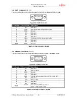
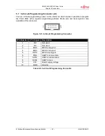
Страница 31: ... Flash MCU with a special programming adapter Mode pins and reset signal is also available at this connector Figure 5 5 In Circuit Programming Connector Pin Number Pin Signal Description 1 NC Not used 2 NC Not used 3 MD0 MCU mode pin 0 4 MD2 MCU mode pin 2 5 INITX MCU reset signal 6 SIN4 UART4 receive data 7 SOT4 UART4 transmit data 8 SCK4 UART4 clock 9 VCC Board supply voltage 10 GND Ground Table...

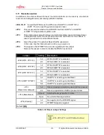
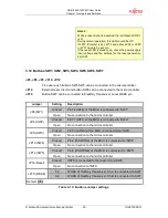
Страница 32: ...P15_2 OCU2 TOT2 JP61 EN A 21 9A P27_1 AN17 LED D8 71 22B P15_3 OCU3 TOT3 JP43 STBN B 22 9B P27_2 AN18 LED D9 72 22C P22_0 RX4 INT12 JP 5 CAN A 23 9C P27_3 AN19 LED D10 73 23A P22_1 TX4 JP 8 CAN A 24 10A P28_0 AN8 74 23B P24_0 INT0 JP4 SW1 25 VDD5 VDD5 75 3A B C VSS5 GND 26 3A B C VSS5 GND 76 VDD5 VDD5 27 10B P28_1 AN9 77 23C P24_1 INT1 JP6 SW2 28 10C P28_2 AN10 78 24A P24_2 INT2 29 11A P28_3 AN11 ...

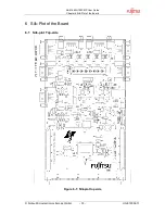
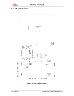
Страница 33: ...SK 91465X 100PMC User Guide Chapter 6 Silk Plot of the Board Fujitsu Microelectronics Europe GmbH 33 UG 910056 11 6 Silk Plot of the Board 6 1 Silk plot Top side Figure 6 1 Silk plot top side ...

Страница 34: ...SK 91465X 100PMC User Guide Chapter 6 Silk Plot of the Board UG 910056 11 34 Fujitsu Microelectronics Europe GmbH 6 2 Silk plot bottom side Figure 6 2 Silk plot Bottom side ...

Страница 35: ... 01 Emulator debugger main unit MB2198 10 DSU cable EMA MB91V460A 00x Emulation Pod including MB91V460A EMA MB91V460A 100 FlexRay extension board EMA MB91465X NLS 100M20 Emulator probe cable for MB91F465X MCU NQPack100SD ND Socket for package FPT 100P M20 Tokyo Eletech Corp www tetc co jp e_tet htm HQPack100SD Header for NQPACK100SD MB91460 Series MB91V460A MB91460 Series Evaluation chip MB91F465X...

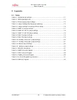
Страница 36: ...jumper settings 17 Table 3 6 UART B LIN A jumper settings 18 Table 3 7 UART C LIN B jumper settings 19 Table 3 8 CAN A jumper settings 19 Table 3 9 CAN B jumper settings 19 Table 3 10 FlexRay Channel A jumper settings 20 Table 3 11 FlexRay Channel B jumper settings 21 Table 3 12 Reset Jumper Settings 22 Table 3 13 Buttons Jumper settings 23 Table 5 1 MCU Pin Connectors 27 Table 5 2 UART Connector ...

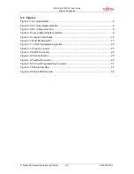
Страница 37: ...tage selection 9 Figure 2 4 Low voltage adapter selection 9 Figure 2 5 Jumper Coordinates 12 Figure 3 1 MCU Mode Switch 13 Figure 4 1 J4 Flash programming socket 26 Figure 5 1 Power Connector 27 Figure 5 2 UART Connector 28 Figure 5 3 CAN Connector 29 Figure 5 4 FlexRay Connector 29 Figure 5 5 In Circuit Programming Connector 31 Figure 6 1 Silk plot top side 33 Figure 6 2 Silk plot Bottom side 34 ...

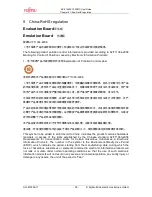
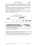
Страница 38: ...保使用期限有可能 比整个产品本身的环保使用期限短 应到期按产品维修程序更换那些消耗件和零部件 以保证 所申明的整个产品的环保使用期限 本产品在使用寿命结束时不可作为普通生活垃圾处理 应被单独收集妥善处理 请注意 环保使用期限50年的指定不是与产品的耐久力 使用期限或任何担保要求等同的 This symbol to be added to all EIO sold to China indicates the product contains hazardous materials in excess of the limits established by the Chinese standard SJ T11363 2006 Requirements for Concentration Limits for Certain Hazardous Substances in Electron...

Страница 39: ...azardous substances name and concentration 有毒有害物质 有毒有害物质 有毒有害物质 有毒有害物质或元素 或元素 或元素 或元素 Hazardous substances name 部件 部件 部件 部件名称 名称 名称 名称 Component Name 铅 铅 铅 铅 Pb 汞 汞 汞 汞 Hg 镉 镉 镉 镉 Cd 六价铬 六价铬 六价铬 六价铬 Cr VI 多溴联苯 多溴联苯 多溴联苯 多溴联苯 PBB 多溴二苯醚 多溴二苯醚 多溴二苯醚 多溴二苯醚 PBDE SK 91465X 100PMC x o o o o o O 表示该有毒有害物质在该部件所有均质材料中的含量均在 表示该有毒有害物质在该部件所有均质材料中的含量均在 表示该有毒有害物质在该部件所有均质材料中的含量均在 表示该有毒有害物质在该部件所有均质材料中的含量均在SJ T1136...

Страница 40: ...erät wieder zurück Zur Entsorgung schicken Sie das Gerät bitte an die folgende Adresse Fujitsu Microelectronics Europe GmbH Warehouse Monzastraße 4a 63225 Langen Valid for European Union Countries According to the European WEEE Directive and its implementation into national laws we take this device back For disposal please send the device to the following address Fujitsu Microelectronics Europe Gm...

Отзывы: