SK-91465X-100PMC User Guide
Chapter 3 Jumpers and Switches
© Fujitsu Microelectronics Europe GmbH
- 19 -
UG-910056-11
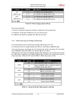
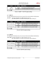
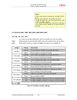
Jumper
Setting
Description
Closed
Vs of LIN B is powered by the board
JP60
(VBAT_B)
Open
No voltage supply to Vs of LIN B
Default: grey
Table 3-7: UART “C”/ LIN “B” jumper settings
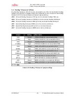
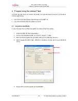
3.7 CAN “A”
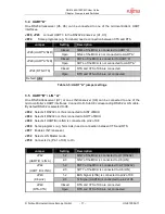
One high-speed CAN-transceiver can be connected to the microcontroller’s CAN interface.
JP5, JP8
connects a CAN-port to the CAN-transceiver (U2, X1).
If the CAN interface is not used then the jumpers should be left open.
Jumper
Setting
Description
Closed
RX4 of the MCU is connected to CAN”A” (X1)
JP5 (CAN”A”RxD)
Open
RX4 of the MCU is not connected to CAN”A”
Closed
TX4 of the MCU is connected to CAN”A” (X1)
JP8 (CAN”A”TxD)
Open
TX4 of the MCU is not connected to CAN”A”
Default: grey
Table 3-8: CAN “A” jumper settings
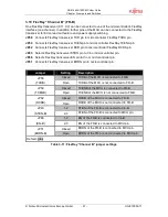
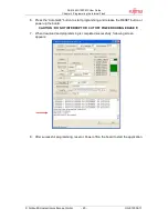
3.8 CAN “B”
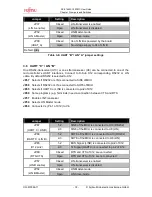
One high-speed CAN-transceiver can be connected to the microcontroller’s CAN interface.
JP15, JP16 connects a CAN-port to the CAN-transceiver (U4, X2).
If the CAN interface is not used then the jumpers should be left open.
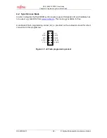
Jumper
Setting
Description
Closed
RX0 of the MCU is connected to CAN”B” (X2)
JP15 (CAN”B”RxD)
Open
RX0 of the MCU is not connected to CAN”B”
Closed
TX0 of the MCU is connected to CAN”B” (X2)
JP16 (CAN”B”TxD)
Open
TX0 of the MCU is not connected to CAN”B”
Default: grey
Table 3-9: CAN “B” jumper settings

