


48
Service Supplement TX600 S3
SCSI backplane
Settings
5.4
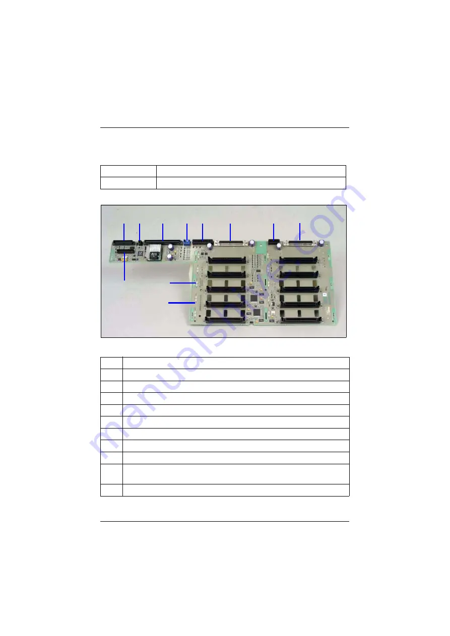
SCSI backplane
Figure 32: Connector assignment on the SCSI backplane (view from the front panel)
Part number:
Same as order number (FSC part)
Order number:
SNP: A3C40058014
Item
Description
A
Connector for control panel (X17)
B
Power supply connector for the CD/DVD drive (X15)
C
Connector for system board (X18)
D
Connector for I
2
C bus cable (X21)
E
Connector “B” for the fans (X20)
F
Connector for SCSI channel “A” (X7)
G
Connector “A” for the fans (X19)
H
Connector for SCSI channel “B” (X1)
I
Back side: Power supply connection (X13); coming from power
backplane
J
Back side: Power supply connection for the tape drives (X14)
Table 3: Assignment of the connectors on the SCSI backplane
(part 1 of 2)
A
C
E
F
G
H
I
J
K
D
B