background image

SX960 S1

Operating Manual

9

1

Preface

The PRIMERGY SX960 S1 storage blade is used as a storage subsystem for 
the PRIMERGY BX400 S1 and BX900 S1 blade server. 

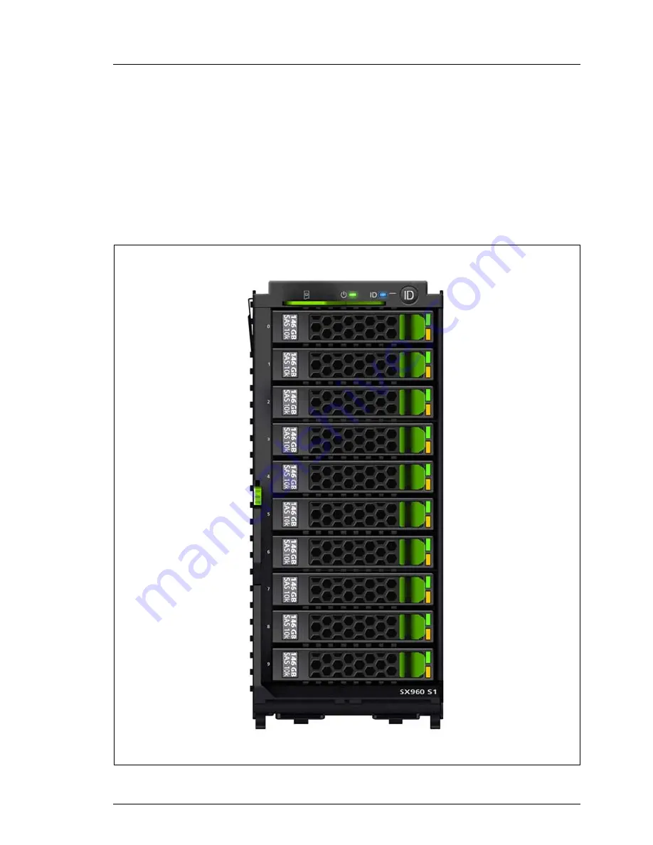
The storage blade comes with 10 bays for 2.5-inch SAS or SATA HDD/SSD 
modules and occupies two bays in the system unit. Up to two SX960 S1 storage 
blades can be installed per BX400 S1 and BX900 S1 system unit.

Figure 1: PRIMERGY SX960 S1 storage blade

Содержание PRIMERGY SX960 S1

Страница 1: ...Operating Manual English PRIMERGY SX960 S1 Storage Blade Operating Manual February 2011 ...

Страница 2: ...kumentation mbH 2011 Pfad C Programme FCT tim_app tim_local work PICHOL OBJ_DOKU 9390 001 fm Copyright 2011 Fujitsu Technology Solutions GmbH All rights reserved Delivery subject to availability right of technical modifications reserved All hardware and software names used are trademarks of their respective manufacturers The contents of this manual may be revised without prior notice Fujitsu assum...

Страница 3: ...n the mouse and keyboard are limited life components Use of these components beyond their operating life may result in electrolyte leakage or depletion potentially causing emission of foul odor or smoke As a guideline in a normal office environment 25 C operating life is not expected to be reached within the maintenance support period 5 years However operating life may be reached more quickly if f...

Страница 4: ...ce follows the guidelines of Voltage Dip Immunity of Personal Computer issued by JEITA the Japan Electronics and Information Technology Industries Association Technology controlled by the Foreign Exchange and Foreign Trade Control Law of Japan Documents produced by Fujitsu may contain technology controlled by the Foreign Exchange and Foreign Trade Control Law of Japan Documents which contain such ...

Страница 5: ...SX960 S1 Operating Manual Only for the Japanese market I Although described in this manual some sections do not apply to the Japanese market These options and routines include CSS Customer Self Service ...

Страница 6: ...Operating Manual SX960 S1 cognitas Gesellschft für Technik Dokumentation mbH 2011 Pfad C Programme FCT tim_app tim_local work PICHOL OBJ_DOKU 9390 001 fm ...

Страница 7: ...15 2 2 Electrostatic sensitive device label 17 2 3 CE conformity 18 2 4 FCC Class A Compliance Statement 18 2 5 RFI suppression 19 2 6 Notes on transportation 19 2 7 Environmental protection 20 3 Installation 23 3 1 Installation procedure 24 3 2 Unpacking a storage blade 24 3 3 Installing removing a storage blade in from the system unit 25 4 Operation 33 4 1 Control and display elements 33 4 2 Put...

Страница 8: ... fm 5 Hot plug components 37 5 1 Hot plug drives 37 5 2 Removing installing the dummy module 40 5 3 Installing removing the HDD SSD module 41 6 Optional Installation of a BBU 45 6 1 Installing the BBU 46 6 2 Replacing the BBU 55 7 Troubleshooting and tips 59 7 1 Drives reported as dead when starting system 59 7 2 Added drive reported as defective 60 Index 61 ...

Страница 9: ...em for the PRIMERGY BX400 S1 and BX900 S1 blade server The storage blade comes with 10 bays for 2 5 inch SAS or SATA HDD SSD modules and occupies two bays in the system unit Up to two SX960 S1 storage blades can be installed per BX400 S1 and BX900 S1 system unit Figure 1 PRIMERGY SX960 S1 storage blade ...

Страница 10: ...Notes and Regulations manual 安全上のご注意 for the Japanese market Warranty manual 保証書 for the Japanese market Returning used devices manual and Service Desk leaflet サポート サービス for the Japanese market I PRIMERGY manuals are available in PDF format on the ServerView Suite DVD 2 The ServerView Suite DVD 2 is part of the ServerView Suite supplied with every server If you no longer have the ServerView Suite ...

Страница 11: ... MB D2616 to back up the memory contents of the RAID controller in the event of power failure 1 4 Notational conventions The following notational conventions are used in this manual Text in italics indicates commands or menu items Quotation marks indicate names of chapters and terms that are being emphasized Ê describes activities that must be performed in the order shown V CAUTION pay particular ...

Страница 12: ...kJ h max Product safety and ergonomics International IEC 60950 1 2 Europe Safety EN 60950 1 2 ergonomics ISO 9241 3 EN 2941 3 EK1 ITB 2003 2007 UL 60950 1 2 USA Canada CSA C22 2 60950 1 03 Taiwan CNS 14336 China GB 4943 Electromagnetic compatibility International CISPRA 24 Europe EN 55022 EN 55024 EN 61000 3 2 EN 61000 3 3 ETS 300386 USA Canada 47CFR part 15 Class A ICES 003 Taiwan CNS 13438 Class...

Страница 13: ...fety Global CB Europe ENEC Germany GS CE USA Canada CSAUS CSAC Japan VCCI China Taiwan BSMI Height 204 mm chassis height 210 5 mm Depth 508 mm 525 mm incl lever Width 90 5 mm 2 bays in the system unit Environment class 3K2 Environment class 2K2 EN 60721 IEC 721 Part 3 3 EN 60721 IEC 721 Part 3 2 Temperature Operation 3K2 5 C 35 C Transport 2K2 20 C 60 C Humidity 10 85 non condensing ...

Страница 14: ...14 Operating Manual SX960 S1 Preface cognitas Gesellschft für Technik Dokumentation mbH 2010 Pfad C Programme FCT tim_app tim_local work PICHOL OBJ_DOKU 9392 001 fm ...

Страница 15: ...uld only be performed by service staff Any failure to observe the guidelines in this manual and any unauthorized opening or improper repairs could expose the user to risks electric shock fire hazards or damage the equipment Please note that any unauthorized opening of the storage blade will void the warranty and exempt the manufacturer from all liability During installation and before operating th...

Страница 16: ...d Check that the rated voltage specified on the device s ID plate is the same as the local line voltage Never connect or disconnect data transmission lines during a storm lightning hazard Make sure that no objects e g bracelets or paper clips fall into or liquids spill into the device risk of electric shock or short circuit Note that proper operation of the system in accordance with IEC 60950 1 DI...

Страница 17: ...nents containing ESDs You must always discharge yourself of static charges e g by touching a grounded object before working The equipment and tools you use must be free of static charges Only touch the components at the positions highlighted in green touch points Do not touch any exposed pins or conductors on a component Use a grounding cable designed for this purpose to connect yourself to the sy...

Страница 18: ...cations However there is no warranty that interference will not occur in a particular installation If this equipment does cause harmful interference to radio or television reception which can be determined by turning the equipment off and on the user is encouraged to try to correct the interference by one or more of the following measures Reorient or relocate the receiving antenna Increase the sep...

Страница 19: ...ve radio noise suppression in accordance with EC Guideline 89 336 EEC Products which meet this requirement are accompanied by a certificate to that effect issued by the manufacturer and or bear the CE mark Products which do not meet this requirement may be operated only with the special permission of the BZT Bundesamt für Zulassungen in der Telekommunikation 2 6 Notes on transportation I Only tran...

Страница 20: ...ndard_servers index html for the EMEA market http primeserver fujitsu com primergy concept for the Japanese market Energy saving information Devices that do not need to be constantly switched on should be switched off until they are needed as well as during long breaks and after completion of work Packaging information This packaging information doesn t apply to the Japanese market Do not throw aw...

Страница 21: ...ils regarding the return and recycling of devices and consumables within Europe can also be found in the Returning used devices manual via your local Fujitsu branch or from our recycling center in Paderborn Fujitsu Technology Solutions Recycling Center D 33106 Paderborn Tel 49 5251 525 1410 Fax 49 5251 525 32 1410 The device must not be disposed of with domestic waste This device is labeled in com...

Страница 22: ...22 Operating Manual SX960 S1 Important notes cognitas Gesellschft für Technik Dokumentation mbH 2010 Pfad C Programme FCT tim_app tim_local work PICHOL OBJ_DOKU 9393 001 fm ...

Страница 23: ...y and heat Make sure that the storage blade is acclimatized for the time indicated in this table before putting it into operation In table Acclimatization time the temperature difference refers to the difference between the operating environment temperature and the temperature to which the storage blade was exposed previously outside transport or storage temperature Temperature difference C Minimu...

Страница 24: ...uctions in chapter Important notes on page 15 Do not unpack the storage blade until it is at its installation location You should retain the original packaging of the storage blade for possible further transport Ê Transport the storage blade to the place where you want to set it up Ê Unpack all individual parts Keep the original packaging in case you want to transport the storage blade again appli...

Страница 25: ... not allowed A maximum of two SX960 S1 storage blades can be installed into a system unit BX400 S1 and BX900 S1 Only slots 2 3 and slots 6 7 or slots 4 5 of a BX400 S1 system unit can be fitted with SX960 S1 storage blades They provide the server blade in the adjacent slot to the left with additional disk space see figure 3 Figure 3 Fitting rules for the SX960 S1 storage blade within the BX400 S1 ...

Страница 26: ...e the server blade in the adjacent slot to the left with additional disk space see figure 4 Figure 4 Fitting rules for the SX960 S1 storage blade within the BX900 S1 system unit Combinations of supported HDD SSDs The table below shows the possible combinations of the drive types that can be installed Y supported N not supported SATA BC SATA SAS SSD SATA Y Y N Y BC SATA Y Y Y Y SAS N Y Y Y SSD Y Y ...

Страница 27: ...lectromagnetic compatibility EMC regulations and to ensure sufficient cooling of the system components The power supply unit slots on the back do not necessarily have to be populated To add a SX960 S1 storage blade you first have to remove two dummy blades from the relevant slots Figure 5 Removing the dummy blades Ê Push up the green release levers see arrows and pull the dummy blades out of their...

Страница 28: ...ling the dummy blades Slide each dummy blade with the release lever down into the empty slot until it clicks into place Installing the storage blade The SX960 S1 storage blade can be installed during operation and is recognized by the management blade You must restart the related server blade to enable the storage blade to communicate with the server blade see section Putting the storage blade int...

Страница 29: ...n from the system unit Unlocking and installing the storage blade Figure 6 Unlocking the storage blade Ê Undo the locking mechanism 1 of the release lever Ê Open the release lever 2 Ê Push the storage blade as far as possible into the empty slot 3 0 1 ...

Страница 30: ...the system unit cognitas Gesellschft für Technik Dokumentation mbH 2010 Pfad C Programme FCT tim_app tim_local work PICHOL OBJ_DOKU 9394 001 fm Figure 7 Locking the storage blade Ê Push the release lever up until it clicks into place under the locking lever 1 ...

Страница 31: ...ng the Web interface of the management blade see the user interface description in the manual ServerView Management Blade S1 for PRIMERGY BX400 Blade Server Systems respectively for PRIMERGY BX900 Blade Server Systems Ê Undo the locking mechanism of the release lever Ê Open the release lever Ê Pull the storage blade out of the slot V CAUTION If you have removed a storage blade and have not replace...

Страница 32: ...32 Operating Manual SX960 S1 Installing removing in from the system unit cognitas Gesellschft für Technik Dokumentation mbH 2010 Pfad C Programme FCT tim_app tim_local work PICHOL OBJ_DOKU 9394 001 fm ...

Страница 33: ... the ID card see figure 8 above as far as it will go and push it back in again The ID card contains various system information such as product name serial number and order number in the Japanese market only the product name and the serial number 2 Power indicator green Lights up the left server blade is switched on Does not light the left server blade is switched off 0 2 1 ...

Страница 34: ... when the system has been selected by pressing the ID button 4 To deactivate press the ID button again The ID indicator can also be activated viavia the Management Blade Web interface and the ServerView Operations Manager and the iRMC S2 Web interface and its status is reported to the ServerView Operations Manager and the iRMC S2 4 ID button When the ID button is pressed the ID indicator 3 lights ...

Страница 35: ... HDD SSD inactive drive inactive 2 HDD SSD FAULT orange in conjunction with a RAID controller Does not light no HDD SSD error Lights up HDD SSD faulty or Rebuild stopped drive defective needs replacing a rebuild process was stopped or the HDD SSD module is not correctly inserted Slow flashing HDD SSD Rebuild the data is being restored after changing a drive Fast flashing HDD SSD Identify 햲 햳 ...

Страница 36: ...ing removing a storage blade in from the system unit on page 25 Ê There are two ways of restarting the server blade related to the storage blade By pressing the On Off button on the control panel of the server blade Via the Web interface of the management blade see the user interface description in the manual ServerView Management Blade S1 for PRIMERGY BX400 Blade Server Systems respectively for P...

Страница 37: ...60 S1 storage blade 5 1 Hot plug drives The drives which can be ordered for the storage blade SX960 S1 are supplied already mounted in an installation frame so that defective drives can be replaced and new drives can be added during operation The drive and installation frame together make up the HDD SSD module V CAUTION The drive must not be removed from the installation frame by anyone except a s...

Страница 38: ...res can result in data errors and to a loss of data or to total corruption of the drive Observe the following rules to prevent such problems occurring Only store and transport HDD SSD modules within the limits stipulated in the specification 1 Dummy module 2 Tabs for unlocking the dummy module 3 HDD SSD module installation frame with drive installed 4 Indicators HDD SSD Busy green LED and HDD SSD ...

Страница 39: ...e outside of the drive V CAUTION The HDD SSD module must be acclimatized in its operating environment for an acclimatization time before it is started up for the first time Always set the HDD SSD module down carefully with the large surface facing downwards to prevent it from tipping over Temperature difference C operating environment outside Minimum acclimatization time hours 5 3 10 5 15 7 20 8 2...

Страница 40: ...odule Ê Press both tabs on the dummy module together until the locking mechanism disengages 1 Ê Pull the dummy module out of the slot 2 To install a dummy module follow the same procedure in reverse order V CAUTION Store the dummy module in a safe place If you have removed an HDD SSD module and do not install a new one in its place put the dummy module back in its place for cooling to comply with ...

Страница 41: ...nlocking the HDD SSD module Figure 12 Unlocking the 2 5 inch HDD SSD module Ê Release the locking mechanism as follows 1 Press the two green tabs of the locking lever together 1 2 Pull the handle of the HDD SSD module fully in the direction of the arrow 2 The HDD SSD module is now unlocked 2 1 ...

Страница 42: ...OKU 9396 001 fm Installing the HDD SSD module Figure 13 Installing the HDD SSD module Ê Unlock the HDD SSD module as described in section Unlocking the HDD SSD module on page 41 Ê Carefully push the HDD SSD module into the empty mounting location 1 until it stops Ê Push the handle completely in the direction of the arrow 2 until the locking mechanism engages 0 ...

Страница 43: ...king the HDD SSD module on page 41 Ê Pull the HDD SSD module out a few centimeters Ê Wait for at least 60 seconds I This period is necessary for the RAID controller to recognize that an HDD SSD module has been removed and for the drive to come to a stop Ê Pull the HDD SSD module out completely Ê Install the new HDD SSD module as described in sections Unlocking the HDD SSD module on page 41 and Ins...

Страница 44: ...44 Operating Manual SX960 S1 Hot plug components cognitas Gesellschft für Technik Dokumentation mbH 2010 Pfad C Programme FCT tim_app tim_local work PICHOL OBJ_DOKU 9396 001 fm ...

Страница 45: ... Together with the D2616 controller a Battery Backup Unit BBU can optionally be installed Figure 14 Parts of the BBU delivery Pos Description 1 BBU battery with electronic parts underneath 2 3 screws to fix the BBU holder 3 Cable connecting BBU to controller 0 1 ...

Страница 46: ...ICHOL OBJ_DOKU 10281 001 fm 6 1 Installing the BBU Preparations Ê Remove the storage blade as described in section Installing removing a storage blade in from the system unit on page 31 Figure 15 Opening the storage blade Ê Press down the touch point 1 and push the housing cover in the direction of the arrow as far as it will go 2 Ê Lift off the housing cover 0 ...

Страница 47: ...ng the controller Figure 16 Removing the controller Ê Remove both SAS cables from the controller 1 2 I Do not bend SAS cables Ê Remove the screw 3 Ê Pull the controller out of the contact strip of the interposer board 4 Installation will be done in reverse order 0 1 2 ...

Страница 48: ...me FCT tim_app tim_local work PICHOL OBJ_DOKU 10281 001 fm Removing the interposer board Figure 17 Removing the interposer board Ê Remove the power cable 1 Ê Remove the cable to the control panel 2 Ê Lift up both metal clips 3 as far as they will go Ê Remove the interposer board 4 Installation will be done in reverse order 0 1 1 2 ...

Страница 49: ...e BBU holder is installed below the interposer board see figure 18 Figure 18 Installing the BBU holder Ê Place the holder on the two mushroom shaped metal pins and push it to the left as far as it will go 1 Ê Fix the holder with the delivered screw 2 Removal will be done in reverse order 0 ...

Страница 50: ...OKU 10281 001 fm Connecting the BBU cable Figure 19 Connecting the BBU cable Ê Plug the BBU cable in the connector on the BBU board see pos 1 in figure 19 I The plug of the BBU cable has a number printed on the back Make sure this side of the plug faces down i e is not visible Ê Check whether the cable of the battery is connected to the BBU board see pos 2 in figure 19 0 ...

Страница 51: ...of a BBU Inserting the BBU Figure 20 Inserting the BBU in the holder Ê Insert the BBU in the holder as follows 1 Slide the BBU under the two plastic catches of the holder 1 2 Carefully press it down until the two locking hooks clearly engage see circles ...

Страница 52: ...KU 10281 001 fm Reinstalling the interposer board Figure 21 Reinstalling the interposer board Ê Lift up both metal clips 1 Ê Shift the interposer board into the marked openings see circles of the metal cage Ê Press on the metal clips to fix the interposer board 3 Reinstalling the controller Ê Reinstall the controller Follow the instructions on page 47 in reverse order 1 1 ...

Страница 53: ...ating Manual 53 Optional Installation of a BBU Connecting the BBU cable to the controller Figure 22 Connecting the BBU cable to the controller Ê Connect the BBU cable to the BBU connector of the controller see oval ...

Страница 54: ... Closing the storage blade Figure 23 Closing the storage blade Ê Position the housing cover on the housing approx 1 2 cm from the frame so that it is level on both sides Ê Push the housing cover in the direction of the arrow until it clicks into place Insert the storage blade in the system unit as described in section Installing removing a storage blade in from the system unit on page 29 ...

Страница 55: ...BBU Ê Remove the storage blade from the system unit as described in page 31 Ê Open the storage blade as described on page 46 Figure 24 Removing the BBU Ê Remove the BBU cable from the BBU connector of the controller 1 Ê Press against the two locking hooks and lift the BBU out of it s holder 2 0 0 ...

Страница 56: ...emoving the BBU cable Ê Unplug the BBU cable from the defective BBU board 1 Installing the BBU Ê Plug the BBU cable into the connector on the new BBU board see pos 1 in figure 25 I The plug of the BBU cable has a number printed on the back Make sure this side of the plug faces down i e is not visible Ê Check whether the cable of the battery is connected to the new BBU board see pos 2 in figure 25 ...

Страница 57: ...of the holder 1 2 Carefully press it down until the two locking hooks clearly engage see circles Ê Plug the BBU cable into the connector on the controller see pos 1 in figure 24 on page 55 I The plug of the BBU cable has a number printed on the back Make sure this side of the plug faces down i e is not visible Ê Close the storage blade as described in section Installing the BBU on page 54 ...

Страница 58: ...58 Operating Manual SX960 S1 Optional Installation of a BBU cognitas Gesellschft für Technik Dokumentation mbH 2010 Pfad C Programme FCT tim_app tim_local work PICHOL OBJ_DOKU 10281 001 fm ...

Страница 59: ...r Troubleshooting and tips in the operating manual for your system unit in the chapters for the installed components in the documentation for the connected devices in the help systems of the individual programs used If you do not manage to correct the problem proceed as follows Ê Make a note of the steps you have taken and the situation in which the fault occurred Also make a note of the error mes...

Страница 60: ...r is not configured for this drive The drive was probably installed when the system was switched off Ê Reconfigure the RAID controller for the drive using the corresponding utility Information is provided in the documentation for the RAID controller or Ê Remove and reinstall the drive while the system is switched ON If the drive continues to be shown as defective then replace it see Installing rem...

Страница 61: ...efective 60 dead 59 drive module acclimatization time 23 39 installation frame 41 dummy blade removing 27 dummy module HDD SSD module 40 43 E electrical data 12 electromagnetic compatibility 12 18 EMC regulations 40 43 EMC directive 12 environment class 13 environmental protection 20 error drive defective 60 drive dead 59 ESD devices sensitive to electrostatic discharge 17 F fault drive defective ...

Страница 62: ...0 power indicator 33 product name 33 R RAID controller is not configured for this drive 60 recycling devices 21 regulations and standards 12 reinstalling interposer board 52 removing controller 47 dummy blade 27 interposer board 48 removing BBU cable 55 replacing BBU 55 BBU cable 56 replacing online 43 return of devices 21 RFI suppression 19 S Safety instructions 15 safety standards 12 SAS cables ...

Отзывы: