40
Operating Manual
CX2550 M1
Starting up and operation
6.1.1.1
Control elements
I
The server nodes are controlled via related operating panel areas on the
front side of the CX400 M1 server enclosure. See "FUJITSU Server
PRIMERGY CX400 M1 Server Enclosure Operating Manual".
6.1.1.2
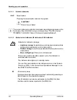
Global error indicator, ID indicator, CSS indicator
RST
Reset button
Pressing the reset button reboots the system.
V
CAUTION!
Risk of loss of data!
Global error indicator (orange)
–
Lights up orange
if a prefailure event has been detected that
requires (precautionary) service intervention.
–
Flashes orange
if an error was detected that requires service
intervention.
–
Does not light up
if there is no critical event.
If the event is still acute after a power cycle, the indicator is
activated after the restart.
The indicator also lights up in standby mode.
You can find more details on the indicated errors in the System
Event Log (SEL), in the ServerView Operations Manager or via
the iRMC S4's Web interface.
ID
ID indicator (blue)
Lights up blue when the system has been selected by pressing on
the ID button in the chassis frontpanel.
The ID indicator can also be activated via the iRMC S4 Web
interface and its status reported to the iRMC S4.
!

