


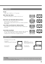


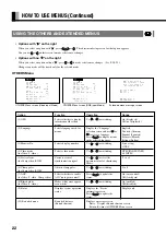


11
Pin No.
Input signal
Pin No.
Input signal
1
Red
9
—
2
Green
10
Ground
3
Blue
11
—
4
—
12
—
5
Ground
13
Horizontal (H) synchronization
6
Ground
14
Vertical (V) synchronization
7
Ground
15
—
8
Ground
Frame
Ground
* Use the RGB synchronization switch to switch between TTL and ANALOG
depending on the types of horizontal (H) and vertical (V) synchronization signals
received through pins 13 and 14, respectively.
Pin No.
Signal
1
DCD (Data Carrier Detect)
2
RD (Received Data)
3
TD (Transmit Data)
4
DTR (Data Terminal ready)
5
GND (Ground)
6
DSR (Data Set Ready)
7
RTS (Request To send)
8
CTS (Clear To Send)
9
RI (Ring Indication)
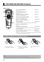
RS-232C terminal (RS-232C)
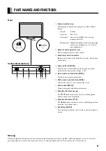
Description of Input Terminals
RGB input terminal (RGB INPUT/mD-sub)


