E-10
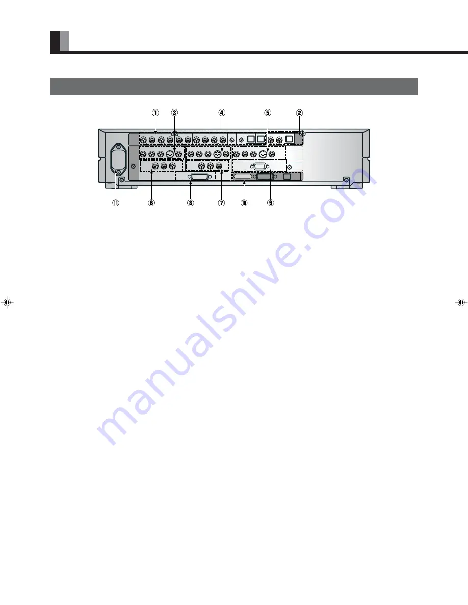
SELECTOR SECTION – REAR
PART NAMES AND FUNCTIONS (Continued)
AUDIO
INPUT
VIDEO1
VIDEO2
VIDEO4
VIDEO5
VIDEO6
RGB1
RGB2
DIGITAL1 DIGITAL2
VIDEO1
PICTURE
INPUT
DIGITAL
AUDIO
OUTPUT
DISPLAY OUTPUT
Y P
B
/C
B
P
R
/C
R
COMPONENT VIDEO
Y P
B
/C
B
P
R
/C
R
COMPONENT VIDEO
Y P
B
/C
B
P
R
/C
R
COMPONENT VIDEO
VIDEO2
VIDEO4
mD-sub
PICTURE
AUDIO
VIDEO5
VIDEO1
Y P
B
/C
B
P
R
/C
R
COMPONENT VIDEO
Y P
B
/C
B
P
R
/C
R
COMPONENT VIDEO
RGB2
RGB1
DVI
S
S
S
1
Audio input terminals
Input audio through the terminals corresponding to the used video input terminals.
* The digital input terminals can be matched as desired with the remote control. (See P. E-27.)
2
Audio output terminals
For use when the sound from an audio system (amplifier) is used.
3
Video1 input terminal
4
Video2 input terminal
5
Video4 input terminal
Connect this terminal to the component video output terminal, S-video output terminal, or video output terminal of your VCR or DVD,
etc.
* See “SETTING THE INPUT TERMINALS” on P. E-41.
6
Video5 input terminal
7
Video6 input terminal
Connect this terminal to the component video output terminal of your DVD, etc.
8
RGB1 input terminal
Connect this terminal to the monitor (DVI-D) output terminal of your PC.
9
RGB2 input terminal
Connect this terminal to the monitor (mD-sub) output terminal of your PC.
0
Display output terminals (Picture/Audio)
Connect these terminals to the picture input terminal and audio input terminals on the display.
A
Power input terminal
Connect this terminal to the power cable supplied with the display.
e04̲psu4h10w(07̲15)j.p65
02.10.4, 0:04 PM
10


