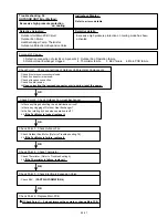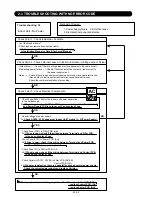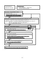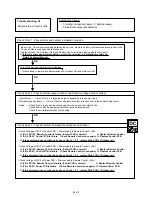
Trouble shooting 35
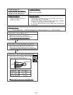
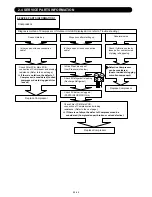
OUTDOOR UNIT Error Method:
Indicate or Display:
Refer to error code table.
Detective Actuators:
Detective details:
Forecast of Cause :
OK
OK
OK
OK
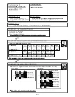
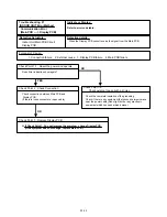
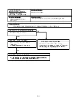
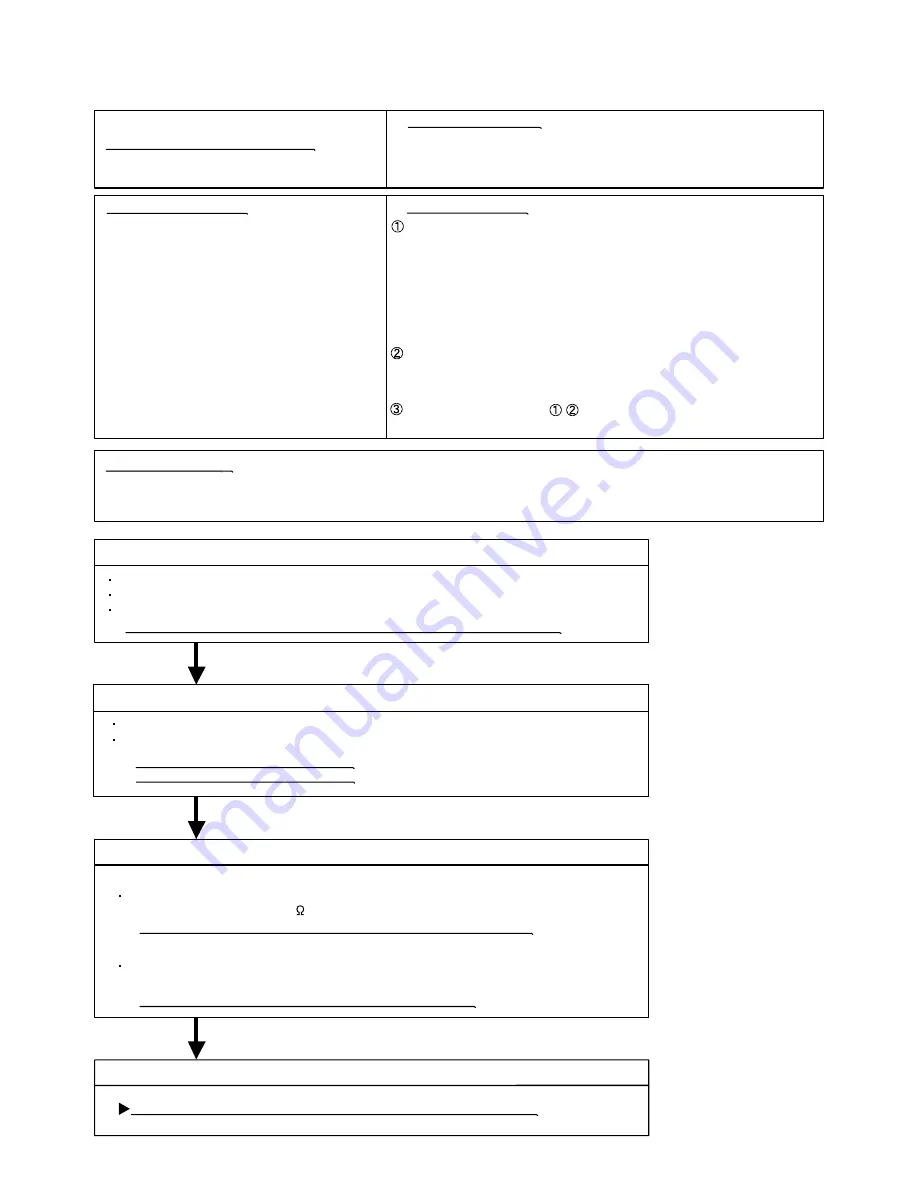
4-way valve error
Outdoor Unit Main PCB Circuit
Heat Exchanger Temperature
Thermistor (middle)
Indoor Temperature Thermistor
4-way valve
The following condition is monitored every one minute after the
compressor operates consecutively for 19 minutes, and 7 min ST
operates when the condition is detected two times in succession.
< Cooling or Dry operation >
[Indoor heat exchanger temp (middle)] - [Room temp] > +10degC
< Heating operation >
[Indoor heat exchanger temp (middle)] - [Room temp] < -10degC
The compressor restarts after 7 min ST is released.
When the continuance operation time of the compressor becomes
19 minutes, it detect difference between the heat exchanger
temperature (middle) and room temperature again.
when protective function repeats five times, the outdoor unit stops
permanently and displays an error.
1. Connector connection failure 2. Thermistor failure 3. Coil failure 4. 4-way valve failure
5. Main PCB failure
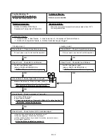
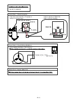
Check Point 1 : Check connection of Connector
Check if connector is removed.
Check erroneous connection.
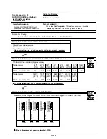
Check if thermistor cable is open.
>>Upon correcting the removed connector or mis-wiring, reset the power.
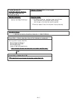
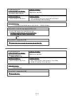
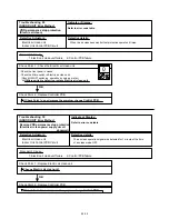
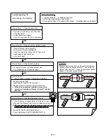
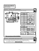
Check Point 3 : Check the solenoid coil and 4-way valve
Remove CN30 from PCB and check the resistance value of coil.
Resistance value is about 1.4k
>>If it is Open or abnormal resistance value, replace Solenoid Coil.
02-39
[ Solenoid coil ]
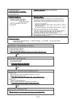
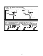
Check each piping temperature,
and the location of the valve by the temperature difference.
>>If the value location is not proper, replace 4-way valve.
[ 4-way valve ]
OK
OK
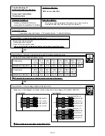
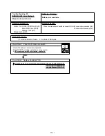
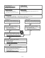
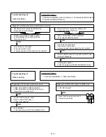
Check Point 4 : Replace Main PCB
If Check Point 1- 3 do not improve the symptom, replace Main PCB.
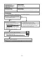
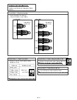
Check Point 2 : Check thermistor
Isn’t it fallen off the holder?
Is there a cable pinched?
>> Check characteristics of thermistor
If defective, replace the thermistor
Содержание Inverter Halcyon ASU12RMLQ
Страница 3: ...1 DESCRIPTION OF EACH CONTROL OPERATION R410A WALL MOUNTED DUCT CASSETTE type INVERTER MULTI ...
Страница 26: ...2 TROUBLE SHOOTING R410A WALL MOUNTED DUCT CASSETTE type INVERTER MULTI ...
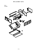
Страница 76: ...3 REPLACEMENT PARTS R410A WALL MOUNTED DUCT CASSETTE type INVERTER MULTI ...
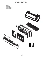
Страница 77: ...REPLACEMENT PARTS 03 01 Models ASU9RMLQ ASU12RMLQ ASU18RMLQ INVERTER ...
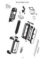
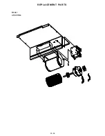
Страница 78: ...REPLACEMENT PARTS 03 02 Models ASU9RMLQ ASU12RMLQ ASU18RMLQ ...
Страница 79: ...Model ARU9RML 03 03 REPLACEMENT PARTS ...
Страница 80: ...Model ARU9RML 03 04 REPLACEMENT PARTS ...
Страница 81: ...Models ARU12RML ARU18RML 03 05 REPLACEMENT PARTS ...
Страница 82: ...Models ARU12RML ARU18RML 03 06 REPLACEMENT PARTS ...
Страница 83: ...Models ARU9RML ARU12RML ARU18RML 03 07 REPLACEMENT PARTS ...
Страница 84: ...40 Models AUU9RML AUU12RML AUU18RML REPLACEMENT PARTS ...
Страница 85: ...41 Models AUU9RML AUU12RML AUU18RML CONTROL UNIT REPLACEMENT PARTS ...
Страница 86: ...38 CASSETTE TYPE DECORATION PANEL UTG UFUB W REPLACEMENT PARTS ...
Страница 88: ...REPLACEMENT PARTS 03 08 Model AOU24RML AOU24RML1 ...
Страница 89: ...REPLACEMENT PARTS 03 09 Model AOU24RML AOU24RML1 ...
Страница 90: ...REPLACEMENT PARTS 03 10 Model AOU24RML AOU24RML1 ...
Страница 91: ...REPLACEMENT PARTS 03 11 Connector BLACK GREEN BLUE RED YELLOW WHITE Connector RED Model AOU24RML AOU24RML1 ...
Страница 92: ...REPLACEMENT PARTS 03 12 Model AOU36RML AOU36RML1 ...
Страница 93: ...REPLACEMENT PARTS 03 13 Model AOU36RML AOU36RML1 ...
Страница 94: ...REPLACEMENT PARTS 03 14 Model AOU36RML AOU36RML1 ...
Страница 95: ...REPLACEMENT PARTS 03 15 Connector BLACK GREEN BLUE RED YELLOW WHITE Connector RED Model AOU36RML AOU36RML1 ...
Страница 141: ...4 APPENDING DATA R410A WALL MOUNTED DUCT CASSETTE type INVERTER MULTI 1 PT CHART ...
Страница 145: ...1116 Suenaga Takatsu ku Kawasaki 213 8502 Japan GS06082006 JUN 2006 Printed in Japan ...

