


146
M
Motor
control
circuit
Phase data
Hi-Z or L
C
ent
The space motor is rotated as follows:
The MPU reads phase excitation data from ROM.
The rotation direction and initial excitation phase are set in the control register of the stepping motor
control circuit and simultaneously current specification data is written to the current specification register
as needed.
An internal interrupt is caused to the MPU every step and, when needed, the excitation time and current
specification data are changed to control the stepping motor.
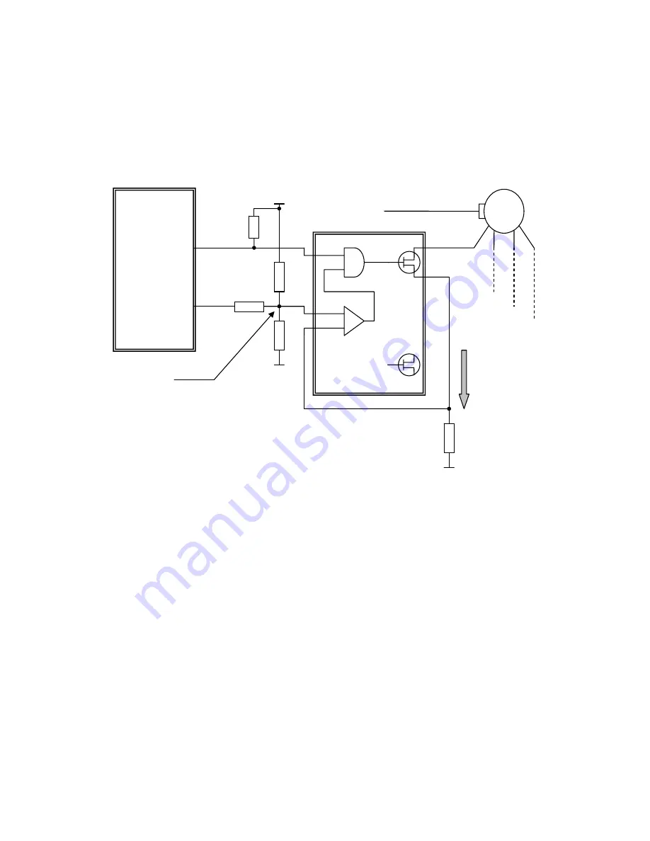
Figure 5.3.16 shows the space motor drive circuit.
MB90706
+5V
SPCOM
HIC1(SLA7025M)
SPM0-3
FET
SPI1,2
Comparator
Reference voltage SG1
FET
Current I
R
SG2
Figure 5.3.16 Space motor drive circuit
The space motor uses a constant current drive circuit as shown in Figure 5.3.16
The constant current drive IC is a hybrid IC used exclusively for motor driving.
The MB90706 stepping motor control circuit outputs SPM0 to SPM3 as phase data.
When the output signal is Hi-Z(H), the FET in the HIC goes on to supply current to the motor phase.
Current I flows to SG2 through resistor R. Voltage level IR for the SG2 when current I flows into resistor
Ris compared with the reference voltage in the HIC comparator.
When IR exceeds the reference voltage, the comparator output and phase signal are ANDed in the HIC
to turn off the FET and thereby control flowing current constant.
The reference voltage is generated by pressure division of the resistor as shown in Figure 5.3.16.
The reference voltage is changed at the pressure division resistor by current control signals SPI1 and
SPI2 from the motor control circuit, and thus output current is controlled.
Содержание Impact 3650
Страница 112: ...112 ...


