

En-8
5. INSTALLING DRAIN PIPES
CAUTION
Install the drain pipe in accordance with the instruc-
•
tions in this Installation Manual and keep the area warm
enough to prevent condensation. Problems with the pip-
ing may lead to water leaks.
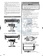
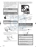
Install the drain pipe with downward gradient (1/50 to 1/100)
•
and so there are no rises or traps in the pipe.
Use general hard polyvinyl chloride pipe (VP25) [outside
•
diameter 38 mm].
During installation of the drain pipe, be careful to avoid
•
applying pressure to the drain port of the indoor unit.
When the pipe is long, install supporters.
•
Do not perform air bleeding.
•
Always heat insulate (8 mm or over thick) the indoor side of
•
the drain pipe.
Drain pipe
Arrange the drain pipe
lower than this portion.
Lifted up
Wave
End in water
Supporter
1.5 to 2
Good
Bad
Bad
Unit : m
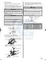
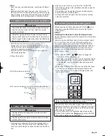
Install insulation for the drain pipe.
(1)
Cut the included insulation material to an appropriate size
and adhere it to the pipe.
Drain pipe
Insulation for drain pipe
(To be obtained locally. Length
should be at least 8 mm.)
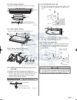
Drain pipe insulation (accessories)
Indoor unit (drain port)
Drain pipe insulation
Drain pipe
No gap
10 or over
Indoor unit
Unit : mm
If “
(2)
○
1 Right rear piping” : fasten the drain pipe with VT wire
so that the pipe slopes correctly within the indoor unit.
Indoor unit (rear view)
VT wire
Drain hose
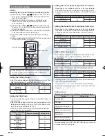
If the drain hose will not be connected to the right rear
(3)
piping, cut the hole cover at the points indicated in Fig. (a),
and attach it to the piping hole as shown in Fig. (b).
(a)
Cut x 5
Hole cover
(b)
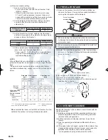
4.4. Installing heat insulation
CAUTION
After checking for gas leaks (refer to the Installation
•
Manual of the outdoor unit), perform this section.
Install heat insulation around both the large (gas) and
•
small (liquid) pipes. Failure to do so may cause water
leaks.
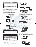
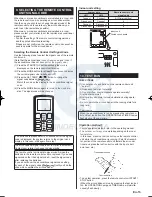
After checking for gas leaks, insulate by wrapping insula-
tion around the two parts (Gas and Liquid) of the indoor unit
coupling, using the coupler heat insulation.
After installing the coupler heat insulation, wrap both ends
with vinyl tape so that there is no gap.
Secure both ends of the heat insulation material using Binder.
And finally fix connection pipe (Liquid) to connection pipe
(Gas) by rolling vinyl tape over coupler heat insulation (Gas)
and coupler heat insulation (Liquid).
Indoor unit
Indoor unit
Indoor unit
Coupler heat insulation (Large)
Connection pipe (Gas)
Connection pipe (Liquid)
Coupler heat insulation (Small)
Binder (Large)
No gap
Coupler heat
insulation
Binder (Small)
Connection pipe (Gas)
Connection pipe (Liquid)
Vinyl tape
When using an auxiliary pipe, make sure that the Binder
•
used is insulated in the same way
CAUTION
There should be no gaps between the insulation and the
•
unit.
1125-9379122009.indd 8
2008/11/26 7:57:05
www.enindel.com


