background image

55

3

SETUP AND MAINTENANCE

y

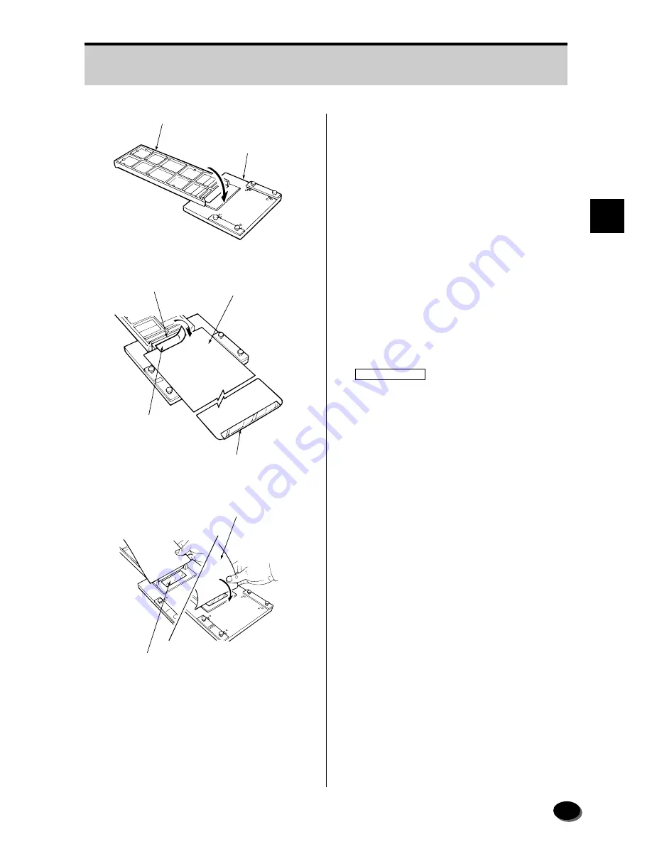
Place the control strip holder on the leader
splice stand.

u

Place the control strip leader so that its
trailing end (without vinyl guide) contacts
the end of the control strip and join the
ends with splicing tape for negative film
processing.

IMPORTANT

• Use the specified splicing tape. Use of

improper tape may cause paper jam.

• Cut the splicing tape slightly shorter

than the width of the control strip so that
it does not protrude. If the tape
protrudes or it is too short, a jam may
result.

i

Attach splicing tape to the reverse side as
well and press down on the surface of the
tape to ensure proper adhesion.

GD1310

Control Strip Holder

Leader Splice Stand

GD1311

Control Strip

Control Strip Leader

Splicing Tape

Vinyle Guide

GD1312

Splicing Tape

Control Strip Leader

Содержание FRONTIER 390

Страница 1: ...TRUCTION MANUAL Applied Operating Instructions PP3 B166E2 System Disk Ver 4 0 SP2500 LP2500P DIGITAL MINILAB SCANNER IMAGE PROCESSOR FRONTIER 390 LASER PRINTER PAPER PROCESSOR SP2500 LP2500P Second Edition ...

Страница 2: ...ICE 1 Electro optical mechanical reproduction of this manuscript is strictly forbidden 2 Product innovations may result in specification changes without prior notice UNITED STATES OF AMERICA FCC NOTE This equipment has been tested and found to comply with the limits for a Class A digital device pursuant to Part 15 of the FCC Rules These limits are designed to provide reasonable protection against ...

Страница 3: ...G INSTRUCTIONS 3 SETUP AND MAINTENANCE 4 DAILY MAINTENANCE 5 PERIODICAL MAINTENANCE AND INSPECTION 6 ERROR MESSAGES AND ACTIONTOTAKE 7 PAPER JAMMING 8 NEGATIVE JAMMING IN 135ANL OPTIONAL 9 STREAK MARKS ON PRINTS AND COUNTERMEASURES 10 LIST OF CONSUMABLES 11 INDEX ...

Страница 4: ...15 1 7 Certification and Identification Labels 16 1 7 1 Certification and Identification Label Locations 16 2 ADDITIONAL OPERATING INSTRUCTIONS 19 2 1 Manual Start up 20 2 2 IX240 Strip Film Printing 21 2 3 Back Printing Selection and Custom Setup Back Printing Display 22 2 4 Front Printing 25 2 4 1 Date Time Printing 25 2 4 2 Title Printing 25 2 5 Center Cropping 26 2 6 IX240 size Reversal Film P...

Страница 5: ...leaning 69 3 10 Replenisher Pump Output Measurement 71 4 DAILY MAINTENANCE 75 4 1 Ink Ribbon Replacement 76 4 2 Turning Power OFF in an Emergency 80 4 2 1 Turning Power OFF in an Emergency Mechanical Software Abnormality 80 4 2 2 Manual Shut off of Scanner Power 81 4 2 3 Manual Shut off of Printer Power 81 5 PERIODICAL MAINTENANCE AND INSPECTION 83 5 1 Maintenance Schedule 84 5 2 Power OFF ON 86 5...

Страница 6: ... 1 6 Paper Jammed in Unit 4 5 W 2405 W 2406 149 7 1 7 Paper Jammed at Loop 1 2 3 4 5 151 7 1 8 Remaining Paper Length Adjustment after Removing Jammed Paper 151 7 2 Paper Jammed in Processor 152 7 2 1 Paper Jammed in Processor or Dryer W 2601 152 7 2 2 Paper Jammed in Cutter Section W 2602 157 8 NEGATIVE JAMMING IN 135ANL OPTIONAL 159 8 1 Negative Jamming during Pre scanning 160 8 2 Negative Jammi...

Страница 7: ...es that may adversely affect performance or damage the equipment NOTE NOTE designates those items provisions and supplementary explanations for which it is important to maintain methodical concern and consideration relative to operational procedures 1 1 Safety 6 1 1 1 Basic Operating Precautions 6 1 1 2 Caution regarding Electric Shock 6 1 2 Laser Radiation Safety 7 1 2 1 Laser Radiation Safety 7 ...

Страница 8: ...an those recommended by Fujifilm are used the warranty will be voided z Do not operate the machine with cover open close sensors forced ON while the covers are open These sensors serve as safety switches If they are forced ON the system mistakenly assumes that the open covers are closed making the machine operative and this may expose personnel to hazardous conditions and damage the machine Never ...

Страница 9: ... of laser radiation when the covers are opened Do not press the safety interlocks when these sections are opened Otherwise laser emissions may occur resulting in serious hazards 1 2 2 Laser Warning Label Protective housing labels and its position required by the Section J of Chapter 1 of 21 CFR issued by the U S FDA are shown in the subsections 1 2 2 and 1 8 1 REFERENCE The FDA Food and Drug Admin...

Страница 10: ...wn below is provided with a caution label concerning safety When operating or maintaining the machine take care to avoid burns or other personal injury 1 3 1 Caution Label Locations on Scanner Image Processor 1 3 Safety Indication EZ1257 ...

Страница 11: ...9 1 OPERATIONAL SAFETY AND USE CONDITIONS 9 GD1550 1 ...

Страница 12: ...10 10 GD1559 1 3 2 Caution Label Locations on Printer Paper Processor ...

Страница 13: ...11 1 OPERATIONAL SAFETY AND USE CONDITIONS 11 GD1560 ...

Страница 14: ...12 12 CAUTION Visible laser radiation when open DO NOT STARE INTO BEAM CAUTION Visible laser radiation when open DO NOT STARE INTO BEAM GD1618 1 3 3 Laser Caution Label Locations on Printer ...

Страница 15: ...aintain the ambient room relative humidity within the range of 30 to 70 RH at all times Ventilation Provide a vent close to the processor section and maintain adequate ventilation Illumination 500 lux or lower Maintain room illumination levels so that no more than 500 lux falls on the scanner and printer upper surfaces Should the equipment main body or paper magazine be exposed to direct outside l...

Страница 16: ...er plug immediately and contact your local dealer Do not obstruct air vents Do not place the monitor close to magnetic fields 1 5 2 Main Control Unit To prevent damage to the system abide by the following points Do not install any application software without Fujifilm s consent Do not modify the data structure or data in the hard disk Do not open the main control unit without the consent of a Fuji...

Страница 17: ...ccordance with the ordinances governing the handling of industrial waste products in your locale The P1 R chemical in the CP 48S replenisher cartridge and the Component A of the P1 start up chemical fall into the category of industrial waste Should you have any questions concerning these chemicals consult your service representative Special note should be taken regarding the following properties o...

Страница 18: ... 28 29 30A 346 365 380 400 415V3 N 15 15 12 12 12A 50 60Hz 200 210 220 230 240V 32 32 28 29 30A 200 210 220 230 240V3 23 24 20 21 21A 346 365 380 400 415V3 N 15 15 12 12 12A 50 60Hz FPO US GD1436 1 1 7 Certification and Identification Labels 1 7 1 Certification and Identification Label Locations ...

Страница 19: ...17 1 OPERATIONAL SAFETY AND USE CONDITIONS 17 GD1550 2 ...

Страница 20: ...nter Cropping 26 2 6 IX240 size Reversal Film Print 27 2 7 Black White Negative Printing 28 2 8 1 Frame Image Display Printing 29 2 9 Sort Data Display Setting 31 2 10 Unexposed Frame Detection Level Setup 32 2 11 Tone Adjustment 33 2 12 Selecting Sharpness Level 34 2 13 Monotone Printing 35 2 13 1 Making Monotone Prints from Monotone Film for Color Development 35 2 13 2 Making Monotone Prints fro...

Страница 21: ...fter approximately 10 minutes It normally takes about one hour for the machine to warm up at the start of operation For this reason it is recommended that the weekly timer be used if the next start time is known in advance see the Basic Operating Instructions EZ1192 Start Switch 2 1 Manual Start up ...

Страница 22: ...he strip film into the strip film guide with its leader notch facing the opposite side The film is fed automatically and all frames are pre scanned e Proceed with printing using the same procedure as for cartridge film printing see Basic Operating Instructions EZ1165 Strip Film Guide Notch EZ1211 2 2 IX240 Strip Film Printing ...

Страница 23: ...Custom Setting Display The 135 120 Back Printing IX240 Back Printing or Back Print of Custom Setting Display dialog box appears e 135 120 q Select the back printing contents from 1 to 6 w Select User ID or Private Character box and enter user ID or data using the numeric keys or full keyboard The maximum number of characters is 3 for the user ID and 35 for private characters r IX240 q Select a pri...

Страница 24: ...cation Correction Data Sort No 1 2 3 4 5 6 1 2 3 4 ABC IARRWSSKK CMYDDD SORT F F F F F F CCCCCCCCCCCCCCCCCC SSSSS Sno IARRWSSKK CMYDDD SORT F F F F F F CCCCCCCCCCCCCCCCCC SSSSS SORT PP PP F F F F F F CCCCCCCCCCCCCCCCCC SSSSS SORT YYYMMDD PP PP F F F F F F CCCCCCCCCCCCCCCCCC SSSSS MM MM IARRWSSKK CMYDDD SORT AAA F F F F F F CCCCCCCCCCCCCCCCCC SSSSS IARRWSSKK CMYDDD SORT SORT IARRWSSKK CMYDDD MM MM ...

Страница 25: ...on OFF 2 For Correction OFF Confirmation A Full Correction ON B Fixed Graduation ON C For Correction ON Confirmation Graininess Control Level Code Graininess Control X OFF A Normal B Low High definite Process Code RP Tone Face Express 0 OFF Normal 2 OFF High 4 ON Normal 6 ON High Sort No Density Correction CMY Correction Graduation Level Code Level 0 Standard 1 All Hard 2 All Soft 3 Highlight Hard...

Страница 26: ... Front Printing dialog box appears w Select YES or NO for Date and Time Printing Normally select YES If front printing is not desired select NO e Click OK The dialog box disappears 2 4 2 Title Printing q Insert the film into the auto film carrier NC240AG w Select Printing 2 and Front Printing 3 on the menu bar The Front Printing dialog box appears e Select the frame for title printing r Select YES...

Страница 27: ...frame e Press the F2 key F2 The cursor moves to the magnification box r Change the magnification using the and keys To increase magnification To decrease magnification When a large size index print is selected maximum magnification may be less than 42 00 Press the F2 key again to return to the original magnification t Proceed with printing y Select Printing 2 and Cropping 7 on the menu bar The Cen...

Страница 28: ... The dialog box disappears Nega on the left end of the printing status bar changes to Rev r Proceed with printing using the same procedure as for normal printing see Basic Operating Instructions t To return to color negative printing select Scanner Op 3 and Original Select 1 on the menu bar Select Color Negative in the Input Type box and click OK The dialog box disappears Control returns to the co...

Страница 29: ...og box disappears Nega on the left end of the printing status bar changes to B W e Proceed with printing using the same procedure as for normal printing see Basic Operating Instructions r To return to color negative printing select Scanner Op 3 and Original Select 1 on the menu bar Select Color Negative in the Input Type box and click OK The dialog box disappears Control returns to the color negat...

Страница 30: ...appears w Press the FILM DRIVE key to select the film feed mode FILM DRIVE Pressing the key alternates the mode from one to the other as shown below Semi Auto Manual Semi The Manual mode can be selected only in the 1 Frame mode Feed the frame by pressing the key or return to the previous frame by pressing the key after fine scanning in the Manual mode e Insert the film Follow this procedure to cha...

Страница 31: ...ctions The W 1701 message appears after the key is pressed when the last frame is displayed t Click OK The film is fed out from the auto film carrier The film can be returned to the previous frame by pressing the key after clicking Cancel y To return to the 6 frame display screen press the Shift and F4 keys twice at the same time Shift F4 Change the frame mode before loading the film Or select Sca...

Страница 32: ... number move the cursor to Sort No Change enter the new sort number and click OK The sort number of the next order will be changed to new number If the preceding print order has not been sorted the sort number cannot be changed Press the SORT key before doing this procedure Follow this procedure to display the sort data of the last order and change the sort number 2 9 Sort Data Display Setting ...

Страница 33: ... the index print IX240 size and 135 size reorder with index 1 Detects unexposed frames The frame lines of the unexposed frames are printed in the index print 2 Does not detect unexposed frames The images of the unexposed frames are printed in the index print 3 The image of the unexposed frames in the middle of the film and the frame lines of consecutive unexposed frames at the end of the film are ...

Страница 34: ...lect the desired tone from 0 to 6 in the Tone box r Select YES or NO in the Hypertone box t Click OK If OK is clicked the selected frame is printed with the tone setup If Hold is clicked the tone setup is held until the SORT key is pressed or an auto sort is done The dialog box disappears Follow this procedure to select the tone adjustment and to turn the hypertone function ON or OFF 2 11 Tone Adj...

Страница 35: ...ar e Select the desired level from 1 to 7 shown in the Level box r Click OK If OK is clicked the selected frame is printed with the sharpness setup If Hold is clicked the sharpness setup is held until the SORT key is pressed or an auto sort is done The dialog box disappears Follow this procedure to select the sharpness level 2 12 Selecting Sharpness Level ...

Страница 36: ...rocess continued appears If this message appears select a film channel by following the steps below q Click Printing 2 and Special Film CH Select 5 on the menu bar The Special Film CH Selection dialog box appears w Select the film channel e Click OK The monotone images are displayed on the monitor screen w Proceed with printing using the same procedure as for normal printing see Basic Operating In...

Страница 37: ...ction list appears in the box t Select the desired correction in the box and click OK The selected frame is printed with the monotone correction after you click OK If the Hold button is clicked the monotone correction specification is held for the following frames The dialog box disappears The color image on the monitor changes to a monotone image y Proceed with printing using the same procedure a...

Страница 38: ...ection dialog box appears r Move the cursor to RP tone Correction and select Yes or No t Click OK If OK is clicked the frame is printed with the RP tone correction If Hold is clicked the correction setup is held for the following frames until the SORT key is pressed or auto sort is done The dialog box disappears RP tone Reversal Print tone prints can be made from a negative film by using the RP to...

Страница 39: ...ect OFF ON 5 on the menu bar The Auto Correct ON dialog box appears t To turn auto correction ON click OK If the Hold button has been clicked auto correction is not turned ON until the SORT key is pressed or an auto sort is done The dialog box disappears Sometimes auto color correction does not function for color biased films or films taken under different kinds of light sources fluorescent light ...

Страница 40: ...this paper feed function to advance the fogged paper by the required number of print lengths 2 16 Paper Feed q On the printing screen press Alt and F1 keys at the same time Alt F1 The Paper Process Selection screen appears w Click 3 Feeding A Confirmation dialog box appears e Click OK The paper is fed by a single print length The dialog box disappears ...

Страница 41: ...ing Selection q Select Image Correct 4 and Custom Setting No Select 6 on the menu bar The Custom Setting No Selection dialog box appears w Click and select the custom setting number Click Master to return to 0 Master Setup e Follow the steps below to view the custom setting condition selected The custom setting cannot be changed in this menu q Click Condition The Corr Level Tone Hypertone panel ap...

Страница 42: ...Click the Sharpness Grain Control tab to view the setting The Sharpness Grain Control panel appears r Click the High def Density Correct tab to view the setting The High def Density Correct panel appears t Click OK The condition panel disappears r Click OK The dialog box disappears ...

Страница 43: ...e made with the custom setup condition selected y Select the Image Correct 4 and Custom Setting No Select 6 on the menu bar The Custom Setting No Selection dialog box appears u Click Master The printing condition returns to the master condition 0 i Click OK Operation returns to the normal printing mode after auto sorting ...

Страница 44: ...or r Press the START ENTER key The W 1932 message appears t Click Output The film is fine scanned y Proceed with printing The W 1932 message does not appear after second pressing the START YES key 2 18 Forced Printing The image can be printed on paper that does not match the selected size For example 89 0mm 127mm size print can be printed on 127mm width paper but the print 127 0mm 127mm has 19mm l...

Страница 45: ... Control Strip Processing 54 3 5 1 Control Strip Preparation 54 3 5 2 Control Strip Processing 56 3 5 3 Control Strip Storage and Handling Precautions 59 3 6 Scanning Lamp Reflector Replacement 60 3 7 Scanning Lamp Position Adjustment 66 3 8 135 Light Source Aperture Table 68 3 9 135ANL Optional Negative Catcher Section Cleaning 69 3 10 Replenisher Pump Output Measurement 71 ...

Страница 46: ...ance menu screen by doing the procedure below 3 1 Setup and Maintenance Menu Screen q On the Main Menu select 4 Setup and Maintenance and click OK The Login dialog box appears w Click OK The menu for 4 Setup and Maintenance appears ...

Страница 47: ...START The 411 Production Information 1 screen appears The information can be changed by selecting Negative Reversal Digital Image or All in the Input Type box r To clear the data follow the steps below q Click Clear The Clear production information dialog box appears w Click OK The production data are erased and the clearing date is displayed in the From box ...

Страница 48: ...48 t Click OK Operation returns to the 4 Setup and Maintenance screen y Select END 1 on the menu bar Operation returns to the Main Menu screen ...

Страница 49: ...ts use position e Select 2 Print Condition Setup and Check See section 3 1 r Select 1 Paper Condition Setup t Click START The 421 Paper Condition Setup screen appears When loading new paper follow the procedure below to set the new paper condition 3 3 Paper Condition Setup Magazine Lock Lever GD1304 Large size Tray GD1378 ...

Страница 50: ...ome out press the Dens Measure button i Adjust the guide of the densitometer according to the width of the condition setup print Densitometer Operation Panel When an error occurs press the orange RESET switch Densitometer Guide EZ634 Indicator Lamp Ready Measuring Error POWER Green ON ON ON READY Green ON Blink OFF ERROR Red OFF OFF ON ...

Страница 51: ...measurement of density is automatically started and the measurement result is displayed 1 Click OK The density measurement result disappears If the density measurement result is NG the message shown on the left appears Perform steps 6 to 10 again until the result becomes OK Densitometer Condition Setup Print EZ635 EZ636 START Button ...

Страница 52: ...52 2 Click Cancel The 4 Setup and Maintenance screen appears 3 Select END 1 on the menu bar Control returns to the Main Menu ...

Страница 53: ... Condition Setup and Check menu See section 3 1 w Select 2 Processor Temperature Check e Click START The 422 Processor Temperature Check screen appears r Click OK Operation returns to the 4 Setup and Maintenance screen t Select END 1 on the menu bar Control returns to the Main Menu screen ...

Страница 54: ...trip package and place it on the control strip holder with the seam facing up and then put them both in a dark box Close the dark box cover e Insert your hands into the sleeves of the dark box take one control strip out of the inner bag and insert it into the control strip holder as shown in the figure Push it in until it reaches the far end r Fold over the open end of the inner bag to prevent fog...

Страница 55: ...d splicing tape Use of improper tape may cause paper jam Cut the splicing tape slightly shorter than the width of the control strip so that it does not protrude If the tape protrudes or it is too short a jam may result i Attach splicing tape to the reverse side as well and press down on the surface of the tape to ensure proper adhesion GD1310 Control Strip Holder Leader Splice Stand GD1311 Control...

Страница 56: ...on 3 1 w Select 3 Control Strip Processing and then click START The 423 Control Strip Processing screen appears e Click OK to start the control strip processing The message Processing the control strip appears The message Set Holder appears on the operation panel on the printer 3 5 2 Control Strip Processing ...

Страница 57: ...rooves in the No 2 crossover rack y Insert the end of the control strip leader into the No 1 crossover rack so that the line lies lower than the index line on the crossover rack u Turn the roller guide toward the dryer side GD1313 Control Strip Holder Rib Grooves in No 2 Corssover Rack GD1314 Control Strip Leader Line Index Line GD1315 Roller Guide ...

Страница 58: ...twice The processor starts and control strip processing begins After about 4 minutes the control strip is fed out into the large size tray The message Control strip processing is completed appears on the screen 1 Remove the control strip holder from the processor 2 Click OK The message is cleared Processor Cover GD1306 Large size Tray GD1378 ...

Страница 59: ...eference and a correction factor chart for the reference strip Process a control strip and measure the reflection densities R G B with a densitometer to verify the processing solution performance IMPORTANT Place the control strips inside a plastic bag and store them in a freezer 10 C 14 F or below Storage at room temperatures will lead to deterioration in performance Moisture condensation occurs i...

Страница 60: ...ints always wear clean gloves when handling the lamp bulb and reflector 3 6 Scanning Lamp Reflector Replacement q Open the 3 Scanner Adjustment Maintenance menu See section 3 1 w Select 1 Lamp Reflector Replacement e Click START The 431 Lamp Reflector Replacement screen appears r Click OK The print lamp goes out and a lamp cooling count down starts ...

Страница 61: ...wn at the left appears t Release the latch and open the light source section cover y Disconnect the safety thermostat connector and lamp connector by releasing the locks Latch Light Source Section Cover EZ870 GD1421 Lock Lock Safety Thermostat Connector Lamp Connector ...

Страница 62: ...st IR filter bracket by loosening the screw 0 Remove the reflector by loosening the screw 1 Remove the scanning lamp 2 Use a soft dampened cloth to gently wipe any dirt off the reflector If the dirt cannot be removed replace the reflector Lamp Unit EZ874 GD1422 First IR Filter Bracket Screw GD1423 Reflector Scanning Lamp EZ873 Lamp Unit Screws ...

Страница 63: ...e retaining plate 4 Install a new lamp IMPORTANT To prevent fingerprints always wear clean gloves when handling the lamp 5 Reinstall the first IR filter bracket while aligning its tang with the slot and tighten the screw Slot Tang First IR Filter Bracket Screw EZ1261 EZ581 Screw Retaining Plate Stoppers EZ589 ...

Страница 64: ...ngaging its notches with the two pins on the filter unit 7 Hang the lamp unit as shown and tighten the two screws 8 Connect the two connectors Safety Thermostat Connector Lamp Connector EZ877 Pins Notches Lamp Unit EZ875 Screws EZ876 ...

Страница 65: ...Adjustment see section 3 7 135 Light Source Aperture Table see section 3 8 120 Light Source Aperture Table If 120 size films are printed with the MFC10Y multi film carrier Scanner Correction and Upkeep Printing of the Pre operational Check see Basic Operating Instructions If the lamp does not light after replacement the safety thermostat may be malfunctioning In this case consult a technical repre...

Страница 66: ...ent screen appears t Turn the right side adjusting screw first and then the front adjusting screw using the 3 mm hexagonal wrench so that the green graph on the screen goes to maximum If the red graph area increases turn the adjusting screws in the opposite direction y Click OK 3 7 Scanning Lamp Position Adjustment Right Side Adjusting Screw Hexagonal Wrench 3 mm Front Adjusting Screw EZ935 ...

Страница 67: ...tenance menu u Perform 135 Light Source Aperture Table see section 3 8 120 Light Source Aperture Table If 120 size films are printed with the MFC10Y multi film carrier Scanner Correction and Upkeep Printing of the Pre operational Check see Basic Operating Instructions ...

Страница 68: ...3 135 Light Source Aperture Table r Click START The 433 135 Light Source Aperture Table screen appears t Click Start The machine prepares and displays the light source aperture table y Click OK Control returns to the 4 Setup and Maintenance menu u Select END 1 on the menu bar Control returns to the Main Menu screen 3 8 135 Light Source Aperture Table ...

Страница 69: ...r Section Cleaning screen appears e Remove the auto film carrier NC135AG r Insert the cleaning tape into the negative catcher section with its matte surface facing down t Click Cleaning while holding the cleaning tape The feed rollers on the negative catcher section rotate 3 9 135ANL Optional Negative Catcher Section Cleaning GD142 Auto Film Carrier NC135AG GD143 Cleaning Tape ...

Страница 70: ...70 y Hold the cleaning tape until the feed rollers stop u Click End Control returns to the 4 Setup and Maintenance menu i Click End 1 on the menu bar Control returns to the Main Menu screen ...

Страница 71: ...ured value for P1R 3 10 Replenisher Pump Output Measurement Reduced replenisher pump output may result in improper processing and a drop in level of solution in the processing tank Processing solutions may irritate the eyes and skin When handling processing solutions wear protective goggles a rubber apron rubber gloves rubber boots and other protective gear as appropriate to prevent any solution f...

Страница 72: ...plenisher nozzle into the PS sub tank i Place the measuring cylinder on a level surface read and record the output amount o Pour the replenisher solution from the measuring cylinder into the waste recovery tank 0 Select the Measured value box for PS R and enter the recorded output value using the numeric keys or the and keys 1 Repeat steps 5 through 11 for P1W The machine automatically measures an...

Страница 73: ...ND MAINTENANCE 2 Click OK Operation returns to the 4 Setup and Maintenance screen 3 Select END 1 on the menu bar Control returns to the Main Menu screen 4 Reinstall the sub tank cover 5 Clean the measuring cylinder ...

Страница 74: ...ment of consumables and emergency power OFF procedures 4 1 Ink Ribbon Replacement 76 4 2 Turning Power OFF in an Emergency 80 4 2 1 Turning Power OFF in an Emergency Mechanical Software Abnormality 80 4 2 2 Manual Shut off of Scanner Power 81 4 2 3 Manual Shut off of Printer Power 81 ...

Страница 75: ...y twice Paper is rewound into the magazine e Turn the knob clockwise and open the printer right door r Open the printer left door 4 1 Ink Ribbon Replacement When the printing on the back of the prints becomes faint replace the ink ribbon cassette as follows GD1317 Printer Right Door Knob GD1485 GD1318 Printer Left Door ...

Страница 76: ...ate u Remove the ink ribbon cassette assembly i Remove the ink ribbon cassettes from the bracket o Remove the drive coupling from the knob Do not discard the drive tab or bracket GD1319 Screw Back Printing Unit GD1320 Lock Ink Ribbon Cassette Assembly Retaining Plate Rear Ink Ribbon Cassette Bracket Drive Coupling Knob Front Ink Ribbon Cassette EZ667 ...

Страница 77: ...rify that the drive coupling is correctly inserted into the groove 3 Install the ink ribbon cassette assembly 4 Align the drive hole in the ink ribbon cassette with the drive tab on the printer by turning the knob counterclockwise while pressing it New Ink Ribbon Cassette Bracket Drive Coupling EZ668 Bracket Front Ink Ribbon Cassette Drive Coupling Groove Knob EZ669 GD1321 Ink Ribbon Cassette Asse...

Страница 78: ...nting unit to the left and tighten the screw 7 Close the printer left door 8 Turn the knob clockwise close the printer right door and then turn the knob counterclockwise GD1322 Retaining Plate GD1323 Back Printing Unit Screw GD1324 Printer Right Door Printer Left Door Knob ...

Страница 79: ... 2 2 Manual Shut off of Scanner Power e Press the START switch to start up the system If the problem persist or if an abnormality occurs again consult your technical representative 4 2 Turning Power OFF in an Emergency 4 2 1 Turning Power OFF in an Emergency Mechanical Software Abnormality When operation freezes try removing and reinstalling the film carrier If this does not solve the problem foll...

Страница 80: ...iately and consult your technical representative 4 2 3 Manual Shut off of Printer Power If a strange odor or unusual sound emanates abnormal heat is generated or smoke appears from the printer processor follow the steps described below immediately and consult your technical representative q Turn OFF the built in circuit breaker w Turn the power switch to STANDBY e Turn OFF the main power circuit b...

Страница 81: ...r 89 5 4 Cleaning the Scanner Power Supply Section Air Filter 90 5 5 Cleaning the Printer Section Air Filters 91 5 6 Cleaning the Printer Power Source Section Air Filters 92 5 7 Cleaning the Processing Solution Cooling Air Filters 93 5 8 Dryer Section Air Filter 94 5 9 Cutter Loop Sensor Cleaning 95 5 10 Replacing the Circulation Filters 96 5 11 Washing the Processing Racks 98 5 12 Cleaning the Fi...

Страница 82: ...13 Section 5 14 Item Scanner Scanner Scanner Scanner Processor Scanner Processor Printer Processor Scanner Scanner Scanner Printer Printer Processor Processor Processor Processor Processor Processor Scanner Scanner Processor Schedule Mirror Box Auto Film Carrier NC240AG Auto Film Carrier NC135AG 135ANL Optional Control Strip Magnetic Heads of Auto Film Carrier NC240AG Cutting Waste Punching Waste ...

Страница 83: ...r Power Supply Section Air Filter Film Cooling Air Compressor Filter GD1436 GD1435 Cutter Loop Sensor Processing Racks Circulation Filters Printer Section Air Filters Processing Solution Heater Cooling Air Filters Squeegee Rack Densitometer White Board Printer Power Source Section Air Filters Dryer Section Air Filter ...

Страница 84: ...F the main power circuit breaker Power ON q Turn ON the main power circuit breaker w Turn ON the built in circuit breaker e Wait more than ten seconds and then press the START switch to start up the system See section 2 1 5 2 Power OFF ON 5 2 1 Turning OFF ON Scanner Built in Circuit Breaker EZ933 EZ934 START switch EZ1192 ...

Страница 85: ... Turn the power switch to STANDBY e Turn OFF the built in circuit breaker r Turn OFF the main power circuit breaker Power ON q Turn ON the main power circuit breaker w Turn ON the built in circuit breaker 5 2 2 Turning OFF ON Printer GD1284 Power Switch GD1282 Built in Circuit Breaker GD1281 Built in Circuit Breaker ...

Страница 86: ...88 e Turn ON the power switch r Turn the power switch to STANDBY after the letters appears on the operation panel display of the printer GD1283 Power Switch GD1284 Power Switch ...

Страница 87: ...ilter by aligning its tab with the groove in the scanner 5 3 Cleaning the Light Source Section Air Filter The light source section air filter is provided to ensure that clean air is introduced into the light source section Clean it once a week IMPORTANT If the light source air filter is clogged the temperature in the light source section will rise shortening the service life of the scanning lamp L...

Страница 88: ...ction air filter is clogged the temperature in the power supply section will rise causing circuit boards to malfunction q Turn OFF the power to the scanner See subsection 5 2 1 w Remove the scanner power supply section air filter e Wash the air filter in tap water r Allow the air filter to dry completely then reinstall it in the reverse order of removal EZ1841 Scanner Power Supply Section Air Filt...

Страница 89: ...ly then reinstall them into the holders t Reinstall the holders in the reverse order of removal 5 5 Cleaning the Printer Section Air Filters The printer section air filters are provided to ensure that clean air is introduced into the printer section Clean them once a week IMPORTANT If the printer section air filters are clogged the temperature in the electrical equipment section will rise causing ...

Страница 90: ...e temperature in the power supply section will rise causing power supply circuit board to malfunction q Turn OFF the power to the printer See subsection 5 2 2 w Remove the filters and holders by pressing the lock tabs e Wash the air filters in tap water Replace the filter with a new one if it is damaged r Allow the air filters to dry completely then reinstall them into the holders t Reinstall the ...

Страница 91: ...letely then reinstall them into the holders t Reinstall the holders in the reverse order of removal 5 7 Cleaning the Processing Solution Cooling Air Filters The processing solution cooling air filters are provided to ensure that clean air is introduced into the processing solution cooling fans Clean them once a week IMPORTANT If the processing solution cooling air filters become clogged temperatur...

Страница 92: ...ilter to dry completely then reinstall it into the holder t Reinstall the holder in the reverse order of removal 5 8 Dryer Section Air Filter The dryer section air filter is provided to ensure that clean air is introduced into the dryer section Clean it once a week IMPORTANT If the dryer section air filter becomes clogged temperature control will be impaired 1890 Air Filter GD1629 Air Filter Air F...

Страница 93: ... INSPECTION q Wipe the lower cutter loop sensor with a clean dry cloth 5 9 Cutter Loop Sensor Cleaning If the cutter loop sensor is dirty the cutter loop will not detect properly Clean the sensor once a week GD1325 Cutter Loop Sensor ...

Страница 94: ...ssing solutions may irritate the eyes and skin When handling processing solutions wear protective goggles a rubber apron rubber gloves rubber boots and other protective gear as appropriate to prevent the any solution from coming in contact with the body Always wash hands well after handling the processing solutions IMPORTANT If the circulation filters are not replaced the circulation of processing...

Страница 95: ...der y Install the holder by aligning its fastening tab with the cutout and turn it 90 degrees clockwise to secure it u Replace the P1 2 P2 1 P2 2 PS1 PS2 PS3 and PS4 filters in the order indicated by repeating steps 3 to 6 i Reinstall the sub tank cover GD1334 Filters Filter Holder Tray GD1278 Fastening Tab Cutout ...

Страница 96: ...ling the processing solutions IMPORTANT If the P1 solution is contaminated with the P2 and or PS solutions it will become unfit for use To prevent solution contamination always attach the contamination prevention cover onto the P1 rack when removing or returning all the processing racks except for the P1 rack Clean the racks in the following order PS4 PS3 PS2 PS1 P2 2 P2 1 P1 2 P1 1 Take special c...

Страница 97: ...acks t Install the contamination prevention cover over the P1 2 and P1 1 racks y Loosen the screw securing the large size tray and remove the tray GD1337 Crossover Racks No 9 No 8 No 7 No 6 No 5 No 4 No 3 No 2 No 1 GD1338 Contamination Prevention Cover GD1339 Screw Large size Tray ...

Страница 98: ...the entire rack Collect the waste in the waste solution collection tank 2 Run warm water 30 to 40 C 86 to 104 F over the rack and thoroughly wash the roller bearing sections and parts that come in contact with the solution in the tank To avoid scalding injuries and rack deformation do not use water hotter than 40 C 104 F IMPORTANT Do not brush the rollers and paper guides or processing marks on th...

Страница 99: ... the same direction as the other knobs on the racks and carefully reinstall the PS4 rack IMPORTANT Reinstall the racks immediately after washing them If the processor is left without the racks in place for a long period water in the solutions will evaporate and the processing performance may be reduced 6 Repeat steps 4 to 15 to wash the PS3 to P2 1 processing racks Hold the contamination preventio...

Страница 100: ...ontamination prevention cover 8 Repeat steps 4 to 13 to wash the P1 2 and P1 1 racks 9 Reinstall the No 1 to No 6 crossover racks in sequential order 0 Reinstall the large size tray and tighten the screw GD1342 Contamination Prevention Cover GD1337 Crossover Racks No 9 No 8 No 7 No 6 No 5 No 4 No 3 No 2 No 1 GD1341 Large size Tray Screw ...

Страница 101: ...tall the squeegee rack while aligning its grooves with the guide pins 2 Secure the squeegee rack with the lock 3 Reinstall the squeegee rack cover then the processor cover GD1329 Squeegee Rack Lock Guide Pins 4 GD1343 Squeegee Rack Cover Processor Cover ...

Страница 102: ...g screw r Remove the air filter from the air filter case 5 12 Cleaning the Film Cooling Air Compressor Filter The film cooling air compressor filter is provided to ensure that clean air is introduced into the compressor Clean it every 3 months Air Filter Section Cover EZ928 Wing Screw Air Filter Case EZ929 Air Filter Air Filter Case EZ930 ...

Страница 103: ...r y Squeeze the air filter and allow it to dry naturally u Reinstall the air filter into the case i Reinstall the filter case with its air intake upward and tighten the wing screw o Reinstall the air filter section cover Air Filter EZ931 Air Filter Case Air Intake Wing Screw EZ932 ...

Страница 104: ...Shift the filter unit to the front and remove it t Remove the filter bracket by unscrewing the screw 5 13 Cleaning the Light Source Optical Filters Clean the light source optical filters every 3 months The light source section becomes very hot during operation Wait until the printing lamp cools down Screw Filter Bracket EZ593 Filter Unit Lock Motor Connector Screws EZ879 ...

Страница 105: ...ng the blower Reinstall the lamp unit u Blow off any dirt or dust adhering to the second IR filter using the blower i Blow off any dirt or dust adhering to the balance filter using the blower o Reinstall the filter bracket and tighten the screw First IR Filter EZ1215 EZ594 Second IR Filter Screws Filter Bracket EZ595 Balance Filters EZ592 ...

Страница 106: ...er unit and tighten the two screws 1 Connect the motor connector 2 Close the light source cover and close the latch 3 Perform Scanner Correction on the Pre operation Check menu Motor Connector EZ1262 Filter Unit Screws EZ1216 ...

Страница 107: ...Turn OFF the power to the densitometer e Remove the white board cover by sliding it to the right while depressing it with thumb 5 14 Cleaning the Densitometer White Board Clean the densitometer white board every 3 months White Board Cover EZ699 GD1433 Densitometer Table GD1434 Densitometer Switch ...

Страница 108: ...10 r Clean the white board with a cotton swab t Reinstall the white board cover y Turn ON the densitometer power u Place the densitometer on the table and push in the table Cotton Swab White Board EZ700 ...

Страница 109: ...th some errors the previous screen returns and the alarm stops when the OK button is pressed with other errors the error status is cleared when the cause of the error is remedied and with still other errors the error should be remedied after stopping the alarm sound by turning the power OFF Errors with the X code are related with software trouble If these error occurs follow the steps below 1 Perf...

Страница 110: ...ime 10min Scanner correction not performed Perform scanner correction in Pre operational Check Carrier not installed Install carrier This film is not processed Printing impossible Remove cartridge Carrier cover opened Close cover Removing cartridge failed Remove cartridge referring to manual Scanner correction cannot be performed because with film or mask exists Take out film or mask Mirror box no...

Страница 111: ...ean mirror box and carrier then perform scanner correction in Pre operational Check Dust adhesion to mirror box or carrier detected during scanner correction Remove carrier then clean mirror box and carrier Abnormal light amount pixels detected during scanner correction Auto light adjustment failed due to high CCD output Consult technical representative Offset cancellation failed Call technical re...

Страница 112: ...as been aborted due to the detection of an error during scanner correction The scanner will be corrected Remove the carrier momentarily then reinsert it Light amount insufficient Lamp may malfunction Check the light source section scanning lamp carrier and the film Film mask not installed Remove carrier and check film mask Focus position adjustment not performed for this film type Consult your tec...

Страница 113: ...ge Remove cartridge and inspect it This cartridge is not processed so cannot be used Fold IPI with unprocessed cartridge This cartridge is not processed so cannot be used Check that cartridge mark is set to 4 Cartridge s door section malfunction Check cartridge Unsupported splice tape detected Replace or correct tape Film is inserted in wrong direction Check direction and side then insert film Fil...

Страница 114: ...cal representative Error occurred in slider control sensor home position Call technical representative Film nip control sensor home abnormality detected Call technical representative Variable film mask control sensor home abnormality detected Call technical representative Cartridge door control sensor home abnormality detected Call technical representative Spool control sensor home abnormality det...

Страница 115: ...p Please wait Takes max 10min Monitoring cancelled due to error occurrence Printing may be cancelled with some frames Check print results Error occurred while creating monitoring images Perform pre scan again Post operational check cannot be started because printer is still processing another job Post operational check not started due to error occurrence in printer Connection with printer failed R...

Страница 116: ...and image processor image processing control failure Call technical representative Communication error occurred between main controller and image processor image processing circuit board GMB malfunction Call technical representative Error occurred in transferring image from scanner to printer Call technical representative Software error Re start scanner and printer Magnification too high Remove fi...

Страница 117: ...rrect Move slider to diffusion plate cleaning position Press SKIP to start scanner correction Moving slider to diffusion plate cleaning position Do not touch slider Mask type incorrectly detected Re install film mask Image file cannot be generated External output cancelled Communication error occurred between scanner and printer Call technical representative Incorrect template Consult technical re...

Страница 118: ...carrier and press OK Setting up the correction table Wait for a moment An error occurred in calling the exposure condition retrieve Return to the state just after the pre scan Selected function cannot be used Insert FD FD not inserted Insert next FD Wrong FD inserted Insert correct FD Reading of control information file failed Selected image cannot be displayed Click OK and resume printing Continu...

Страница 119: ...s Stop Backup data for PU800B cannot be read Backup data for PU800B cannot be written Production information log file not found Create a new file Production information cannot be written into file F DI device registration failed Consult technical representative F DI device registration failed Check the network connections Press Retry to retry or Cancel to cancel Registration to F DI not performed ...

Страница 120: ...equired for Red eye Soft Cross not found or any file s may be corrupted Cannot continue Red eye Soft Cross process Cannot create the files required for Red eye Soft Cross Cannot continue Red eye Soft Cross process Data for Red eye Soft Cross process is wrong This frame cannot be selected Frame No to specify template not matched Select other frame Characters can be entered in selected template Ente...

Страница 121: ...Pre Maintenance data failed Stop sending Pre Maintenance data Service to be exported not selected Couldn t perform pre scan Film ejected Reading print mag fine adjust data Wait Saving print mag fine adjust data Wait Carrier mask and composite type mismatch so pre scan not performed Film is fed out RC50D cannot be used with the present printer process type Check printer process type Frame specified...

Страница 122: ...n Open the upper guide or negative holder cover and remove film then install it in the negative holder again The 135ANL negative holder opening operation abnormal Check the negative holder operation by opening and closing the holder cover If problems persist consult your technical representative Remove film and make sure there is no abnormality Wait until the message disappears Refer to the DI ope...

Страница 123: ...he 135AFC not performed normally Open the carrier cover with the 135AFC set to FRONTIER and remove film Set the film in a waiting position in the negative holder The negative press operation of the 135ANL malfunction Open the carrier cover with the 135AFC set to FRONTIER and open the upper guide or negative holder cover then remove film Re install the film in the negative holder and re install the...

Страница 124: ... continuous process is cancelled Remove the film and install the carrier An error occurred while the 135ANL flash ROM is deleted resulting in the download failure Consult your technical representative An error occurred while writing to the 135ANL flash ROM resulting in the download failure Consult your technical representative A communication error occurred between the 135ANL and the 135AFC Consul...

Страница 125: ...e The 135ANL sensor calibration failed If film remains remove it If not clean the sensor The film currently being processed scan cancelled Continue processing a next film Because the 135ANL upper guide is opened the 135ANL sensor calibration cannot be done Close the upper guide This is the last frame Press OK to feed out film Because the carrier or mask was removed the custom setting information a...

Страница 126: ...ess Output to output forcibly Magazine paper width and print size of index format mismatched Press OK to replace magazine or select other index format If you press Output an incorrect index print will be outputted Template width and magazine paper width mismatched Press OK and replace magazine Press Output to output forcibly The high speed mode cancelled due to error occurrence Printing may be can...

Страница 127: ...be started because printing is in progress or the printed paper remains in the printer If the printed paper remains perform ALL PROCESS Error table item TableItem cannot be omitted Sub system SubSystemID TableFileName Error No NUM Error table items TableItem are incorrect Sub system SubSystemID TableFileName Error No NUM Communication error occurred between scanner and printer Command time out Cal...

Страница 128: ...Cancel to cancel All Process Press OK to perform All Process creating margins Abnormal printer backup memory Call technical representative No problem even if this message appears at the upgrade reversion of the printer software Printer s timer abnormal Scanner time adopted If problems persist call technical representative Laser temperature adjustment not completed in exposure section Please wait T...

Страница 129: ...etected in the unit 2 Call technical representative Hole punch not detected in the unit 3 Call technical representative Hole punch not detected in the unit 4 Call technical representative Paper cannot be drawn from magazine Check the magazine Paper remains in printer Remove paper Laser unit shutter in the exposure section feed unit malfunctions Call technical representative Cutting hole punch in t...

Страница 130: ...nical representative Reservoir paper width guide in the unit 3 malfunctions Call technical representative Paper width guide 4 in the unit 4 malfunctions Call technical representative Paper width guide 5 in the unit 5 malfunctions Call technical representative Roller nip in the exposure section feed unit malfunctions Call technical representative Cutter 1 in the unit 3 and cutter 2 in the unit 4 ma...

Страница 131: ...ing Please wait Printed paper not detected All Process not performed Printed paper too short Save Cut not performed Rewinding paper Please wait Printed paper remains Perform All Process Rewinding request rejected Printer section door opened Close door Roller nip in the feeder unit malfunctions Call technical representative Feeding of paper cannot be continued Remove paper Magazine with different p...

Страница 132: ...mation Call technical representative Abnormal B laser B SHG information Call technical representative R laser R LD temperature adjustment outside specified range Call technical representative G laser G SHG temperature adjustment outside specified range Call technical representative B laser B SHG temperature adjustment outside specified range Call technical representative Abnormal R laser R LD temp...

Страница 133: ...is about to its lifetime No problem for the moment but call technical representative SOS detection failed Call technical representative Electric power failure occurred in the exposure and light source sections If problems persist call technical representative Abnormal frame memory Call technical representative G B laser SHG optimal temperature setting periods Set optimal temperature in Printer Adj...

Страница 134: ...strips remains Paper jamming occurred in the cutter section Remove paper Paper remains in the processor or the dryer section Remove paper Open and Close Processor cover once Paper remains in the cutter section Remove paper Slant sorter malfunctions Call technical representative Horizontal sorter malfunctions Call technical representative Cutter malfunctions Call technical representative Hole punch...

Страница 135: ...l representative PS4 processing tank temperature not rising Call technical representative Dryer section temperature not rising Call technical representative P1 processing tank temperature abnormal Heater turned off Call technical representative P2 processing tank temperature abnormal Heater turned off Call technical representative PS1 processing tank temperature abnormal Heater turned off Call tec...

Страница 136: ...ative PS3 safety thermostat activated Heater turned off Call technical representative PS4 safety thermostat activated Heater turned off Call technical representative Safety thermostat in dryer section activated Heater turned off Call technical representative P1 solution level has fallen Temperature adjustment stopped Refer to manual for guidance P2 solution level has fallen Temperature adjustment ...

Страница 137: ...R size sheets can still be printed without replenishment P2RA replenisher pump or cartridge cleaning valve abnormal Call technical representative About 780 3R size sheets can still be printed without replenishment P2RB replenisher pump or cartridge cleaning valve abnormal Call technical representative About 780 3R size sheets can still be printed without replenishment P1R replenisher pump abnormal...

Страница 138: ... replenishment Solution remains in replenisher tank Call technical representative Replenisher cartridge opening failed Call technical representative Error occurred in replenishment section Call technical representative Drive motor for opening replenisher cartridge abnormal Call technical representative About 780 3R size sheets can still be printed without replenishment PSR lowered Add PSR until me...

Страница 139: ...n W1 waste solution tank full Printing stopped Collect waste solution W2 waste solution tank full Printing stopped Collect waste solution Washing solution level has fallen Replenish it Washing solution empty Add washing solution Incorrect order No Enter correct order No Incorrect sort No Enter correct sort No Incorrect CD ID To continue the operation without entering the CD ID press Run To re entr...

Страница 140: ... sort No cannot be changed during this image export service The sort No was restored to match the order condition The number of image export become maximum Press SORT and continue as a next order Imaging Controller not recognised Perform pre operational check Not enough free space to copy files This order being used Order not found Creating order that already exists was tried Correcting no exist o...

Страница 141: ...do the corrective action for the new error message 7 1 Paper Jammed in Printer 144 7 1 1 Paper Magazine Removal 144 7 1 2 Paper Jammed in Paper Feed Unit W 2401 145 7 1 3 Paper Jammed in Unit 1 W 2402 145 7 1 4 Paper Jammed in Exposure Section Feed Unit W 2403 146 7 1 5 Paper Jammed in Unit 2 W 2404 147 7 1 6 Paper Jammed in Unit 4 5 W 2405 W 2406 149 7 1 7 Paper Jammed at Loop 1 2 3 4 5 151 7 1 8...

Страница 142: ...ared w Turn the magazine lock lever clockwise The paper magazine lock is released e Cut the paper at the exit guide of the magazine 7 1 Paper Jammed in Printer 7 1 1 Paper Magazine Removal Magazine Lock Lever Paper Magazine GD1448 Paper GD1449 ...

Страница 143: ...ght and left doors e Remove the paper from the paper feed unit Paper Feed Unit Loop 1 GD1446 7 1 3 Paper Jammed in Unit 1 W 2402 q Remove the paper magazine see subsection 7 1 1 w Open the printer right and left doors e Cut the paper at loop 1 r Remove the paper from the paper feed unit see subsection 7 1 2 Paper Paper Feed Unit GD1450 ...

Страница 144: ...it Unit 2 Loop 2 GD1444 Paper Unit 1 GD1447 7 1 4 Paper Jammed in Exposure Section Feed Unit W 2403 q Remove the paper magazine see subsection 7 1 1 w Open the printer right and left doors e Follow steps 1 through 4 of Paper Jammed in Unit 1 see subsection 7 1 3 r Cut the paper at loop 2 ...

Страница 145: ...aper from the exposure section feed unit Paper Unit 1 GD1447 Exposure Section Feed Unit Paper GD1445 7 1 5 Paper Jammed in Unit 2 W 2404 q Follow steps 1 through 5 of Paper Jammed in Exposure Section Feed Unit see subsection 7 1 4 w Cut the paper at loop 3 Exposure Section Feed Unit Loop 3 Unit 2 GD1441 ...

Страница 146: ... unit r Push the lever to the left to lower the reservoir loop guide plate t Turn the knob on unit 2 counterclockwise and remove the paper from unit 2 Exposure Section Feed Unit Paper GD1445 Reservoir Loop Guide Plate Lever GD1442 Unit 2 Knob Paper GD1443 ...

Страница 147: ...in Unit 2 see subsection 7 1 5 w Cut the paper at loop 4 reservoir loop e Push the lever to the left to lower the reservoir loop guide plate r Turn the knob on unit 2 counterclockwise and remove the paper from unit 2 Loop 4 Unit 4 Unit 3 GD1439 Reservoir Loop Guide Plate Lever GD1442 Unit 2 Knob Paper GD1443 ...

Страница 148: ...en follow the steps below q Loosen the two screws and remove the guide plate from unit 4 w Remove the paper from unit 4 e Reinstall the guide plate by aligning its holes with the pins on unit 4 and tightening the two screws Unit 4 Paper Knob GD1440 GD1563 Screws Pins Unit 4 Guide Plate GD1564 Paper ...

Страница 149: ...xposure Section Feed Unit 7 1 4 W 2407 Loop 3 Paper Jammed in Exposure Section Feed Unit 7 1 4 Paper Jammed in Unit 2 7 1 5 W 2407 Loop 4 Paper Jammed in Unit 2 7 1 5 W 2407 Loop 5 Paper Jammed in Unit 4 5 7 1 6 7 1 8 Remaining Paper Length Adjustment after Removing Jammed Paper q Measure the length of the paper removed w In menu 451 Paper Magazine Registration subtract the measured length from th...

Страница 150: ...processing solutions wear protective goggles a rubber apron rubber boots and other protective gear as appropriate to prevent any solution from coming in contact with the body Always wash hands well after handling the processing solutions q Remove the processor cover w Remove the squeegee rack cover Processor Cover GD1305 Squeegee Rack Cover GD1327 ...

Страница 151: ... at the processor inlet if it is visible r Release the lock lift the squeegee rack and cut the paper at the No 9 crossover rack t Remove the paper from the squeegee rack GD1575 Paper GD1565 Squeegee Rack Paper GD1566 Paper Squeegee Rack ...

Страница 152: ... 5 cm 2 in and turn the knob counterclockwise until the paper comes out and it can be removed If the knob is too hard to turn the paper may be jammed in the P1 1 rack Remove the P1 1 rack and the paper GD1307 No 2 Crossover Rack No 1 Crossover Rack GD1568 Knob P1 1 Rack GD1569 Paper ...

Страница 153: ...ack approximately 5 cm 2 in and turn the knob counterclockwise If the knob is hard to turn remove the P1 2 rack and the paper 0 Install the contamination prevention cover over the P1 1 and P1 2 racks GD1570 Knob P1 2 Rack GD1571 Paper GD1572 Contamination Prevention Cover ...

Страница 154: ... comes out and can be removed 4 Remove the remaining paper by hand 5 Lift the P2 1 to PS4 racks in this order and turn the knob counterclockwise approximately 20 times to make sure there is no paper in the rack 6 Reinstall the No 4 to No 9 crossover racks 7 Remove the contamination prevention cover 8 Reinstall the No 1 to No 3 crossover racks 9 Reinstall the squeegee rack 0 Reinstall the squeegee ...

Страница 155: ...e processor will be fed out through the dryer section e Wind the paper being fed out r Make sure the cutter loop guide plate is closed If the guide plate is opened insert the control strip leader or upkeep print into the cutter section through the loop section to close it IMPORTANT If the cutter loop guide plate is opened error W 2602 will occur on the next printing GD1576 Paper Loop Guide Plate ...

Страница 156: ...e corrective actions for negative jamming in the 135ANL In the event of negative jamming the 135ANL stops negative feed and an error message appears on the monitor of the scanner 8 1 Negative Jamming during Pre scanning 160 8 2 Negative Jamming during Fine scanning 162 ...

Страница 157: ... Take care not to damage the negative at the loop section e Pull the release lever as shown in the figure to release the pressure cover of the film carrier r Remove the negative from the 135ANL Negative Holder Cover GD157 Upper Guide Lock Release Button Loop Section GD158 GD159 Release Lever Pressure Cover Negative GD160 ...

Страница 158: ... film carrier y Reinstall the film carrier u Click OK on the monitor screen The error message disappears i Reinstall the negatives to the negative holder o Close the upper guide and negative holder cover Film Carrier Pressure Cover Lever GD161 Film Carrier GD162 Upper Guide Negative Holder Cover GD163 ...

Страница 159: ...e figure to release the pressure cover of the film carrier w Open the negative loop guide on the carrier inlet guide and remove the negative from the 135ANL e Remove the negative from the film carrier Release Lever Pressure Cover GD159 Loop Guide Negative GD164 Loop Guide Negative GD165 ...

Страница 160: ... film carrier t Reinstall the film carrier y Click OK on the monitor screen The error message disappears u Reinstall the negatives to the negative holder i Close the upper guide and negative holder cover Film Carrier Pressure Cover Lever GD161 Film Carrier GD162 Upper Guide Negative Holder Cover GD163 ...

Страница 161: ... section describes the corrective actions to take for streake marks on prints 9 1 Types of Streak Marks 166 9 1 1 Pressure Cover Section of Auto Film Carrier 166 9 1 2 Mask Section of Auto Film Carrier 166 9 1 3 Mirror Box 167 9 2 Countermeasures 168 ...

Страница 162: ... distorted due to the movement of the dust caused by the film cooling air Dirt or dust adhering to the film carrier may cause streak marks on prints Streak marks on the prints may run in the same direction as the paper feed 9 1 1 Pressure Cover Section of Auto Film Carrier 9 1 2 Mask Section of Auto Film Carrier Dust adheres to the mask section A thin colored streak mark appears on the print due t...

Страница 163: ...type of streak mark appears when dust is present during the scanner correction at the pre operational check stage but is not present during fine scanning A dark streak mark appears on prints 9 1 3 Mirror Box Dust on the upper surface of the mirror box A diffused contoured streak mark appears on print since the dust is not near the surface of the film ...

Страница 164: ... film carrier NC135AG see Basic Operating Instructions r Clean the inside of the film receiver using a vacuum cleaner t Perform Scanner Correction of 1 Pre operational Check see Basic Operating Instructions 9 2 Countermeasures Vacuum Cleaner Film Receiver EZ1836 If streak marks appear on prints remove the dust or dirt by following the steps below ...

Страница 165: ...169 10 LIST OF CONSUMABLES 10 1 Scanner 170 10 2 Printer Processor 171 ...

Страница 166: ...No 122S0026 Reflector Part No 602S0001 Light Source Section Air Filter Part No 374D895509C ScannerPowerSupplySectionAirFilter Part No 374D890211C GD1550 Product innovations may result in part number and shape changes without prior notice ...

Страница 167: ... Part No 345A9049781 2 pieces Circulation Filter Part No 376G03101 8 pieces Power Source SectionAir Filters Part No 4B5482292 4 pieces Printer Section Air Filters Part No 4B5482292 6 pieces ProcessingSectionHeaterCoolingFilters 5 pieces Part No 4B5482292 Dryer Section Air Filter Part No 376G02021 ...

Страница 168: ...173 11 INDEX 5 1 Index 174 5 2 Index of Basic Operating Instructions 176 ...

Страница 169: ...ement 4 1 IX240 Strip Film Printing 2 2 IX240 size Reversal Film Print 2 6 Laser Caution Label Locations on Printer 1 3 3 Laser Radiation Safety 1 2 1 2 1 Laser Warning Label 1 2 2 List of Consumables 10 Main Control Unit 1 5 2 Maintenance Schedule 5 1 Making Monotone Prints from Color Film 2 13 2 Making Monotone Prints from Monotone Film for Color Development 2 13 1 Manual Shut off of Printer Pow...

Страница 170: ...ort Data Display Setting 2 9 Streak Marks on Prints and Countermeasures 9 Title Printing 2 4 2 Tone Adjustment 2 11 Turning OFF ON Printer 5 2 2 Turning OFF ON Scanner 5 2 1 Turning Power OFF in an Emergency 4 2 Turning Power OFF in an Emergency Mechanical Software Abnormality 4 2 1 Types of Streak Marks 9 1 Unexposed Frame Detection Level Setup 2 10 Washing the Processing Racks 5 11 ...

Страница 171: ... 4 6 General Maintenance 8 Handling Precautions 1 6 1 Index of Basic Operating Instructions High speed Three frame Mode 4 22 Holding Conditions 4 15 Image Frame Display Mode Change 4 5 Index Printing Setup 4 18 Inserting Film 4 8 Internal Structure and Paper Feed 2 2 Interrupting Operation 6 3 6 3 2 IX240 Reorder Printing 4 17 3 IX240 Reprinting with Batch Retrieval of Exposure Conditions 4 16 2 I...

Страница 172: ...Daily Processing Volume Data and Clearing the Data 7 2 6 Reorder Printing 4 17 Replenisher Cartridge Replacement 8 1 Reprinting Exposure Condition Retrieval 4 16 Roll Paper Installation 5 4 Room Conditions 1 4 Safety 1 1 Safety Indications 1 3 Save Cut 4 23 2 Scanner Correction 3 2 6 Scanner Image Processor SP2500 2 1 1 Selected Frame 2 4 1 Selecting Items 2 5 1 Series Scene Printing 4 21 2 Sorter...

Страница 173: ...Building 8th Floor 388 Phaholyothin Road Bangkok 10400 Thailand FUJI PHOTO FILM MALAYSIA SDN BHD Letter Box 3 3rd Floor Office Block 1 Crystal Plaza Lot 4 Jalan 51A 223 46100 Petaling Jaya Selangor Darul Ehsan Malaysia FUJI PHOTO FILM CO LTD TAIPEI OFFICE Rm 601 Hung Chong Bldg No 38 Sec 6 Min Chuan E Rd Taipei 11412 Taiwan FUJI PHOTO FILM CO LTD SEOUL OFFICE 505 19 Kasan Dong Kunchon Gu Seoul Kor...

Отзывы: