background image

11

<Step1>

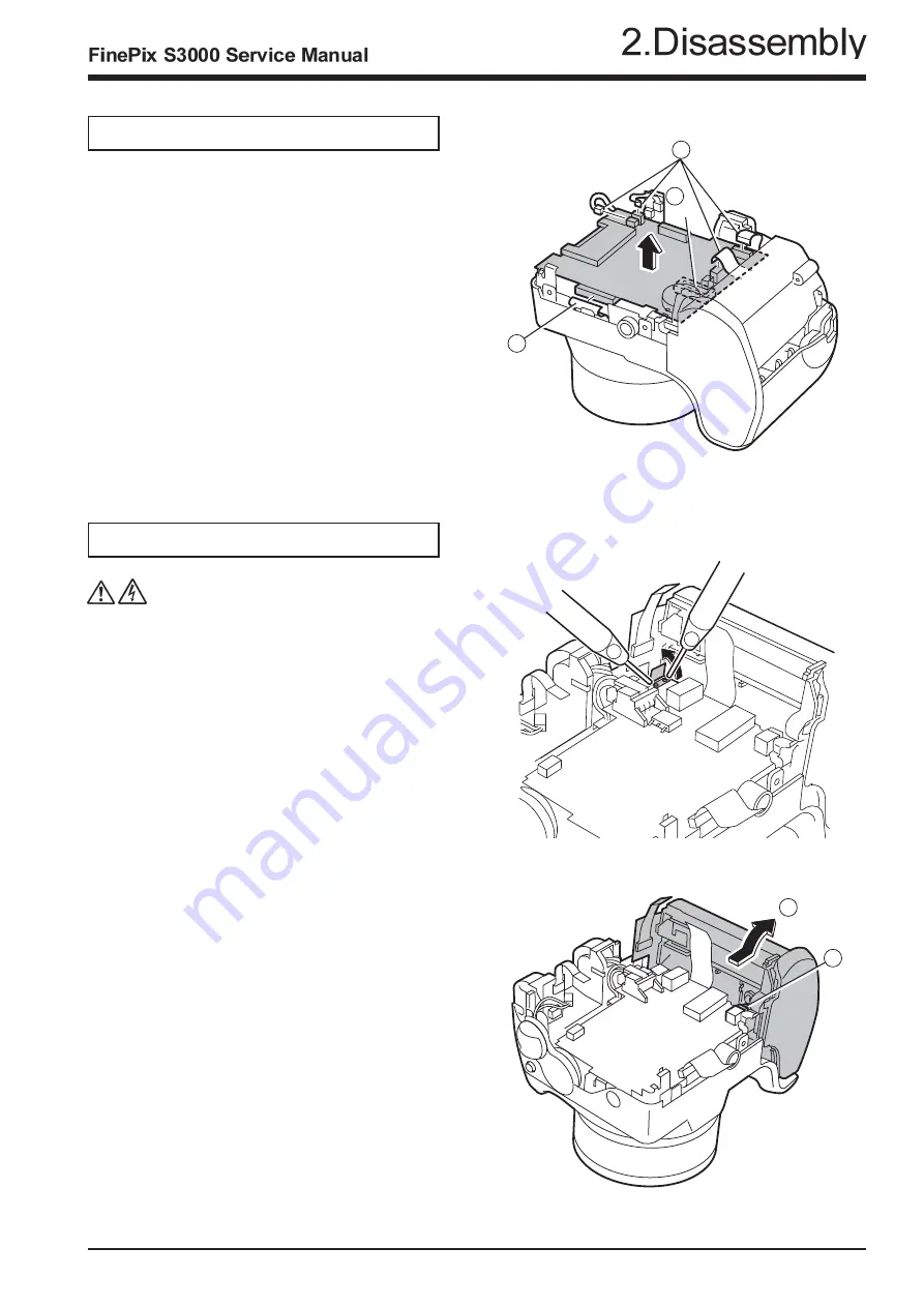
2-5.Removing MAIN PWB ASSY.

Remove in the order indicated by circled numbers.

2-6.Removing BATTERY HOLDER ASSY.

(note)

Make the power lever a turning off mode.

(1) Raise BATTERY HOLDER ASSY in the direction

     of the arrow.

(3) Remove CN601.

<Step1>

Remove in the order indicated by circled numbers.

<Step2>

(1) Peel off the UL tape, and do discharge.

* Reassemble BATTERY HOLDER ASSY in the state

of the power lever off.

1

1

A

2

(1) Remove CN101 CN203, CN301, CN350and CN502.

(2) Remove MAIN PWB ASSY in the direction of the

      arrow while removing the connector in A part.

1

1

1

2

Содержание Finepix S3000

Страница 1: ...in Japan 2004 08 THE COMPONENTS IDENTIFIED BY THE MARK ON THE SCHEMATIC DIAGRAM AND IN THE PARTS LIST ARE CRITICAL FOR SAFETY PLEASE REPLACE ONLY BY THE COMPONENTS SPECIFIED ON THE SCHE MATIC DIAGRAM AND IN THE PARTS LIST IF YOU USE PARTS NOT SPECIFIED IT MAY RESULT IN A FIRE AND AN ELECTORICAL SHOCK ...

Страница 2: ...3000 Service Manual WARNING HIGH VOLTAGE SAFETY CHECK OUT 2 Check the interboard wiring to ensure that no wires are pinched or contact high wattage resistors 2 5A 125V 2 5A 125V RISK OF FIRE REPLACE FUSE AS MARKED ...

Страница 3: ...B Block Circuit 29 3 7 6 LCD Block Circuit 31 3 7 7 MOTOR Block Circuit 31 3 7 8 KEY IO Block Circuit 33 3 7 9 KEY IC Block Circuit 33 3 7 10 CCD Block Circuit 35 3 7 11 MSW Block Circuit 35 3 7 12 KSW Block Circuit 35 3 7 13 RSW Block Circuit 35 3 7 14 VCON Block Circuit 35 4 Adjustment 37 4 1 ImportantpointAdjustmentwhenReplacingMajorParts 37 4 2 TheorderofadjustmentwhenMajorPartsarereplaced 37 ...

Страница 4: ...000 pixels amorphous silicon TFT Flash Auto flash using Effective range Wide Approx 0 3 m 3 5 m 1 0 ft 11 5 ft flash control sensor Tele Approx 0 8 m 3 5 m 2 6 ft 11 5 ft Flash modes Auto Red Eye Reduction Forced Flash Suppressed Flash Slow Synchro Red Eye Reduction Slow Synchro when the pop up flash is stowed Suppressed Flash Self Timer Approx 10 sec timer clock Video output NTSC PAL selectable I...

Страница 5: ...ase 1 LR6 AA size alkaline batteries 4 Adapter Ring 1 Lens Cap 1 Strap 1 Video cable 1 plug 2 5 mm dia to pin plug Approx 1 5 m USB Interface Set 1 CD ROM Software for FinePix SX 1 USB cable with Noise Suppression core 1 Quick start guide for Camera and Software installation 1 Owner s Manual 1 Optional Accessories xD Picture Card DPC 16 16 MB DPC 32 32 MB DPC 64 64 MB DPC 128 128 MB DPC 256 256 MB...

Страница 6: ...es are played at 30 fps JPEG Joint Photographics Experts Group A file format used for compressing and saving color images The compression ratio can be selected but the higher the compression ratio the poorer the quality of the expanded image Motion JPEG A type of AVI Audio Video Interleave file format that handles images and sound as a single file Images in the file are recorded in JPEG format Mot...

Страница 7: ...7 1 3 Names of External Components ...

Страница 8: ...y 2 1 Names of Internal Parts CABI FRONT ASSY LENS UNIT MAIN FRAME ASSY DCST PWB ASSY MAIN PWB ASSY LCD FRAME LCD CONST BATTERY HOLDER ASSY RSW PWB ASSY MSW PWB ASSY STROBE CONST EVF CONST KEY PWB ASSY CABI REAR ASSY VCON PWB ASSY CCD PWB CONST ...

Страница 9: ...o special shape screws 3ULR 1 5X5 0 Because the screws are special shape use the exclusive use jig driver ZJ00583 100 4 Remove CABI REAR while pressing part A in the direction of 3 Reassemble CABI REAR in the state of the Manual camera mode 4 Remove connector CN800 Remove in the order indicated by circled numbers Step1 Step2 ...

Страница 10: ...n the direction of the arrow 3 Remove the lock of CN451 and remove LCD ASSY LCD FRAME to the direction of the arrow Step1 Step2 Remove in the order indicated by circled numbers 2 4 Removing EVF CONST Remove in the order indicated by circled numbers 2 2 1 3 1 Remove CN401 2 Remove CN402 3 Remove EVF CONST in the direction of the arrow Step1 2 3 1 ...

Страница 11: ...RY HOLDER ASSY in the direction of the arrow 3 Remove CN601 Step1 Remove in the order indicated by circled numbers Step2 1 Peel off the UL tape and do discharge Reassemble BATTERY HOLDER ASSY in the state of the power lever off 1 1 A 2 1 Remove CN101 CN203 CN301 CN350and CN502 2 Remove MAIN PWB ASSY in the direction of the arrow while removing the connector in A part 1 1 1 2 ...

Страница 12: ...IN FRAME 6 Remove LENS CONST in the direction of the arrow Step1 2 7 Removing DCST PWB ASSY 1 Remove two screws 2 Remove CN701 CN702 3 Raise DCST PWB ASSY in the direction of the arrow Step1 Remove in the order indicated by circled numbers 4 Remove FPC of LENS CONST in the direction of the arrow Remove in the order indicated by circled numbers Step2 3 1 2 4 1 6 5 2 3 4 ...

Страница 13: ... BASE R in the direction of the arrow 4 Remove one screws 5 Remove the hook of ST BUTTON and pull out ST BUTTON in the direction of the arrow 6 Remove STROBE CONST in the direction of the arrow 7 Pull out two ST SHAFT 8 STOROBE must improve in pop up 9 Remove two screws 10 Remove ST TOP in the direction of the arrow 1 2 4 5 6 7 7 8 10 9 ...

Страница 14: ...emove KEY PWB ASSY in the direction of the arrow Step1 Step1 Remove in the order indicated by circled numbers 2 10 Removing MSW PWB ASSY and RSW PWB ASSY Remove in the order indicated by circled numbers 2 11 Removing KEY PWB ASSY RSW PWB MSW PWB ASSY A Tighten the screw while joining MSW PWB ASSY to A and confirm the thing which MSW PWB ASSY and A are fit 1 hook 2 2 1 3 2 ...

Страница 15: ...CD PWB 1 Remove tow screw 2 Remove the hook of CCD PWB CONST Remove in the order indicated by circled numbers Attention when CCD PWB CONST is exchanged Solder the WIRE HARNESS with new parts when you ex change CCD PWB CONST Cover the solder part by the UL bond SC 608Z FS00095 100 ...

Страница 16: ...BZ120 100 FFC CCD MAIN FZ04949 100 Fold line CAPTON TAPE CCD PWB MAIN PWB 2 13 1 FFC CCD MAIN FERRITE BEADS fixed to FFC Position at 15mm from MAINPWB side Note Do not exceed Fold Line of FFC EMI SHEET fixed to FFC Position at 6mm from MAINPWB side Match Fold Line of EMI SHEET to the left of FFC and paste it ...

Страница 17: ... PWB CONST CCD BLOCK CCD output MAIN PWB ASSY CAM BLOCK Analog to digital conversion of CCD output IC102 CCD driver IC101 MOTOR BLOCK Zoom AF shutter iris drive IC301 POWER ON BLOCK Power supply management IC352 EVF BLOCK EVF control IC403 AUDIO BLOCK Audio signal processing IC501 PROCESS BLOCK USB communication IC202 System control SW detection management IC202 LCD BLOCK LCD relay circuit DCST PW...

Страница 18: ...CD processing IC of the CAM BLOCK so as to obtain a suitable AE AWB and AF 4 LCD UNIT The digital signal sent from the XCS IC203 system LSI is sent to the drive IC of the LCD UNIT via the processing unit on the LCD FPC of the LCD UNIT where LCD drive and LCD panel tonal control are performed 5 Power Supply Block DCDC BLOCK The power supply block is built around the DC IC IC601 It generates the bel...

Страница 19: ...19 3 Schematics 3 4 Block Diagram ...

Страница 20: ...C 1 ZPI_C 2 ZPI_E 3 3V 4 SHUTOU T1 5 SHUTOU T2 6 MID IM1 7 MID IM2 8 SML IM1 9 SML IM2 10 FM A 11 FM B 12 FM A 13 FM B 14 FPI_C 15 FPI_E 16 3V 17 ZPOSI_C 18 ZPOSI_E 19 ZM1 20 ZM2 1 XE 2 TRIG GER 3 XE 4 TRI GGER_C 1 PT 2 PT_GND STROBE CONST STROBE CONST 1 GND 2 VCC 3 VGL 4 VGH 5 FRP 6 COM 7 DH V 8 FB 9 SHL 10 STB 11 VCC 12 SHD B 13 AGND 14 VL ED 15 VL ED 16 AVDD 17 HSYN C 18 YSYN C 19 DCL K 20 DS5 ...

Страница 21: ...21 3 Schematics 3 6 Mounted Parts Diagrams 3 6 1 MAIN PWB ASSY Component Location SIDE A SIDE B ...

Страница 22: ...22 FinePix S3000 Service Manual 3 Schematics 3 6 2 DCDC PWB ASSY Component Location SIDE A SIDE B ...

Страница 23: ...23 3 Schematics SIDE A SIDE B SIDE A SIDE B 3 6 4 MSW PWB UNIT Component Location 3 6 3 CCD PWB CONST Component Location 3 6 5 RSW PWB UNIT Component Location SIDE A SIDE B ...

Страница 24: ...24 FinePix S3000 Service Manual 3 Schematics 3 6 6 VCON PWB UNIT Component Location SIDE A SIDE B 3 6 7 KEY PWB UNIT Component Location SIDE A SIDE B ...

Страница 25: ...25 3 Schematics 3 7 Circuit Diagrams 3 7 1 DCDC Block Circuit ...

Страница 26: ...26 FinePix S3000 Service Manual 3 Schematics 3 7 2 PROCESS Block Circuit ...

Страница 27: ...27 3 Schematics 3 7 3 CAM Block Circuit ...

Страница 28: ...28 FinePix S3000 Service Manual 3 Schematics 3 7 4 EVF Block Circuit ...

Страница 29: ...29 3 Schematics 3 7 5 STROB Block Circuit ...

Страница 30: ...30 FinePix S3000 Service Manual 3 Schematics 3 7 6 LCD Block Circuit ...

Страница 31: ...31 3 Schematics 3 7 7 MOTOR Block Circuit ...

Страница 32: ...32 FinePix S3000 Service Manual 3 Schematics 3 7 8 KEY IO Block Circuit ...

Страница 33: ...33 3 Schematics 3 7 9 KEY IC Block Circuit ...

Страница 34: ...34 FinePix S3000 Service Manual 3 Schematics 3 7 10 CCD Block Circuit 3 7 11 MSW Block Circuit ...

Страница 35: ...35 3 Schematics 3 7 13 RSW Block Circuit 3 7 12 KSW Block Circuit 3 7 14 VCON Block Circuit ...

Страница 36: ... FinePix6800Z Note1 Screw driver D3LUFX88G ZJ00583 100 Disassemble Reassemble Driver for special shape screw Common with the FinePix M603 A310 Discharger ZJ00581 100 Discharge Discharge for Flash Unit X Y Stage for AF adjustment ZJ00611 100 General adjustment LB140 filter holder kit for X Y stage ZJ00653 100 General adjustment For X Y stage FxS3000W PC Soft Ver 2 01 ZJ00741 201 For PC adjustment O...

Страница 37: ...ttern box to 6100 50K 2 Brightness 160 5 cd m2 With LB140 filter Measurement point Center of pattern box Measuring device Brightness meter LS 110 Minolta or similar product How to Measure Brightness Set the filter LB140 against the pattern box With the filter LB140 contacting the pattern box adjust brightness of the pattern box to 160 5 cd m2 1 The camera s reference surface is the front face of t...

Страница 38: ...y chart must be Oxford Gray No 22 made by Su perior with a reflectance of 18 0 7 2 The camera s reference surface for strobe light adjust ment is the front face of the strobe light emitter Fig C Strobe Light adjustment environment 4 Environmental Setup for Video Adjustments Fig D Video adjustments NTSC PAL 4 Adjustments Fig B AF adjustment environment 5 Environmental Setup for LCD Adjustments Fig ...

Страница 39: ... the screen to install the jig driver The jig driver will be saved in C Program Files Fig F 4 7 Installing and Starting the Adjustment Software Step 1 The sdjustment software is downloaded from WEB and software is installed in the PC We have uploaded the PC Adjustment Software ZJ00741 100 zip for FinePixS3000 on our website http fujifilm di intranets com Step 2 ZJ00741 100 zip is a compression of ...

Страница 40: ...ed only to check them Do not rewrite the user program FXS3000W ff If the pro gram is rewritten the adjustment software will not start up Step 1 Step 3 Double click on the FFW exe execute file of the adjust ment software to open the FFW Startup screen Fig 1 Step 2 Click on Settings Fig 1 1 in the menubar of the startup window Then select Mode setting Fig 1 2 from the pull down menu that appears Fig...

Страница 41: ...ox that appears Input the values for PI and P Board Fig 4 1 PIO 0 10 12 14 16 PIO 1 11 13 15 17 Set the Hardware items Fig 4 3 as follows Item Details Debug Mode Default Step 6 Once the above settings have been made click on Apply Fig 4 4 in the Customize dialog box to complete setup This applies the setup therefore setting is unnecessary from the next time forward Note If Disable OKNG display on ...

Страница 42: ...OM write Do not overwrite the user program FXS3000W ff under any circumstances The software will not run if the user program is overwritten Table 1 FFWJ exe Commands Menu Command Details Operation Start Starts the program Stop Stops the program Pause Pauses the program Step 0 Do not use Program Reload Reloads the program ff Select Selects the program ff Edit Edits the program ff Data ad Do not use...

Страница 43: ... up scren Fig 1 The FFW EXE Startup screen Fig 1 is appears Step 2 Press the Enter key of the PC or click on the start button Fig 1 1 in the toolbar The Inithal Screen Fig 2 is appear Step 1 Fig 1 Fig 2 Fig 3 1 After setting the camera to the Jig mode press the Enter key of the PC The Caution When Using the Adjustment Software Fig 3 screen is appears Step 3 ...

Страница 44: ...upgrading Fig 6 After reading the notes press the Enter key of the PC The Jig Mode Setting Procedures screen Fig 4 is appear 1 Set the mode switch to the camera mode 2 Open the slot cover 3 Connect the camera and PC with the USB jig and cable 4 Supply 5 00V 0 01V by using Battery JIG 5 Switch ON the camera power while pressing the shutter button Keep the shutter release button depressed until the ...

Страница 45: ... not be displayed In this case change the settings to ensure that it is displayed 2 In addition to numbers letters are also used in the CCD serial No The data file name is instructed in the same manner in this case 3 Ensure that the CCD serial No is read correctly If the file name is read incorrectly CCD data for another camera will be loaded when this file is used Step 2 Download the ZIP file of ...

Страница 46: ...ile name CCD Serial No Fig CCD4 Fig CCD3 Adjustment Step 1 Select F4 CCD Defect Data Input adjustment on the Adjustment Items Select screen Fig 5 Step 2 Set the xD picture card can be recorded in the camera Set LENS HOOD and LENS CAP in the camera Run the adjustment in accordance with the instructions on the screen Fig CCD3 ...

Страница 47: ...adjustment data to the flash ROM when adjustment has been completed correctly The CCD Defect Data Input adjustment Complete screen appears Fig CCD6 Step 4 Wait until the CCD temperature is steady Fig CCD5 Step 5 Fig CCD5 Fig CCD6 ...

Страница 48: ... F5 CAM Adjustment on the Adjustment Items Select screen Fig 5 The CAM Adjustment Preparation screen appears Step 2 Run the adjustment in accordance with the instructions on the screen Note An error will occur during CAM adjustment and adjustment cannot be completed unless the pattern box is calibrated correctly The CAM Adjustment without filter screen appears Fig CAM2 The CAM Adjustment with filt...

Страница 49: ... the flash ROM when adjustment has been completed correctly The CAM Adjustment Complete screen appears Fig CAM5 Note CAM adjustment may be terminated if adjustment is continued without removing the LB140 filter Always ensure that the LB140 filter is removed before proceeding with adjustment Fig CAM4 4 Adjustments ...

Страница 50: ... 1 Select F6 AF Adjustment on the Adjustment Items Select screen Fig 5 The AF Adjustment Preparation screen appears Step 2 Run the adjustment in accordance with the instructions on the screen Note Always use a 900mm conversion lens The AF Adjustment Start screen appears 4 Adjustments ...

Страница 51: ...51 4 Adjustments Fig AF2 Write the adjustment data to the flash ROM when adjustment has been completed correctly The AF Adjustment Complete screen appears Step 3 Step 4 Fig AF3 ...

Страница 52: ...e Adjustment Step 1 Select F1 Battery Voltage Adjustment on the Adjustment Items Select screen Fig 5 The Battery Voltage Adjustment Preparation screen appears Step 2 Run the adjustment in accordance with the instructions on the screen Step 3 The 3 64V Input screen appears Fig BATT2 4 Adjustments ...

Страница 53: ...ments Step 4 The 5 00V Input screen appears Fig BATT3 Step 5 Write the adjustment data to the flash ROM when adjustment has been completed correctly The Battery Voltage Adjustment Complete screen appears Fig BATT4 ...

Страница 54: ...54 FinePix S3000 Service Manual Step 6 Fig BATT5 4 Adjustments ...

Страница 55: ...al supplied with the jig for details of setting up the LCD automatic adjustment jig with the PC 2 If the LCD flicker image xD Picture card has not been inserted in the camera return to the Jig Mode Setup screen select the Jig mode again and run LCD Adjustment LCD Adjustment is executed Write the adjustment data to the flash ROM when adjustment has been completed correctly The LCD Adjustment Comple...

Страница 56: ...creen Fig 5 The Flash Adjustment Preparation screen appears Step 2 Run the adjustment in accordance with the instructions on the screen The Flash Adjustment Start screen appears Fig FLASH1 Step 3 Write the adjustment data to the flash ROM when adjustment has been completed correctly The Flash Adjustment Complete screen appears Fig FLASH2 ...

Страница 57: ...CI 2746C board in the computer as explained in the instructions for the video adjustment box 2 If the waveform of the brightness signal Y or color signal C does not appear in the WAVE No 0 window during adjustments check the connections of the video adjustment box Fig VIDEO1 4 Adjustments ...

Страница 58: ...he Video Adjustment Preparation screen appears Step 2 Run the adjustment in accordance with the instructions on the screen Write the adjustment data to the flash ROM when adjustment has been completed correctly The Flash Adjustment Complete screen appears Fig VIDEO2 Step 3 Fig VIDEO3 Fig VIDEO4 Close the WAVE No 0 window by close button ...

Страница 59: ...e connected to a single PC the PC will be unable to identify each USB device thus preventing operation 6 Automatically written USB IDs are as follows Item Details Repair Date Date information is acquired from the PC and written Administrator ID C 43 Repair Station U S 61 a SAPPORO 30 0 Canada 62 b SENDAI 31 1 Hawaii 63 c TOKYO 33 3 Taiwan 64 d NAGAYA 34 4 England 66 f OOSAKA 35 5 Germany 67 g HIRO...

Страница 60: ...5 The End Setting Description screen appears Step 3 Run the adjustment in accordance with the instructions on the screen The Destination Setting screen appears Note This example assumes that B US Model has been selected The following screen therefore appears The US Model selected screen appears Fig END1 Fig END2 Step 4 ...

Страница 61: ... Step 6 Step 5 Note This example assumes that H USA has been selected The following screen therefore appears The USA_ID USA screen appears The USB ID Writing screen appears Fig END3 Fig END4 4 Adjustments ...

Страница 62: ...62 FinePix S3000 Service Manual Step 7 Step 6 The FinePix F3000 Adjustment Complete screen appears Fig END5 Fig END6 4 Adjustments ...

Страница 63: ...this archived file from the Web server the extract of the file is necessary In the extract software if the extract of the ZIP form can be done any software is OK Please prepare each one the extract software As the Firmware is different in each model the archived file name is also different Caution Important Download should use xD picture card Please format xD picture card with the camera When the ...

Страница 64: ...mware download according to the instruction of the screen After completing the preparations press the Enter key Start the firmware download The Status confirmation screen appears The download time is about 80 seconds Fig FIRM3 Fig FIRM4 Execute power supply OFF ON according to the instruction of the screen to make the downloaded firmware effective The Download complete screen appears ...

Страница 65: ...e instruction of the screen The camera is started with the new firmware when power is switched OFF ON Press the Enter key to return to the Initial Screen Fig 2 Step 4 Turn on power in the JIG mode and confirm the update to the latest firmware Execute the adjustment related to the repair continuously ...

Страница 66: ...66 FinePix S3000 Service Manual MEMO ...

Страница 67: ...ll angle of field 5 Push and take a picture of the Shutter button 2 Push the Macro botton left 3 Push the Pop up botton Flash Unit Push down 5 Finder LED green lighting orange lighting recording green lighting 6 Movie Recording Movieo photography LCD_ON 1 Change to the movie recording mode 2 Shutter button Half on All on All on Haif on Release 3 Half on after five seconds Release STANDBY must be d...

Страница 68: ...tthepowercablejigwiththecamera 2 Set the power supply voltage 3 Confirm the current at camera power off 4 5 0 1V 1mA or less 15 1 Power SW 2 Initial return factory setting Each model s setting is 5 4 Factory setting is confirmed 3 Slot cover 4 Battery lid 5 Flash unit 6 Lens Shizdou and the barrier must shut 7 ThingwithwhichsurfaceofLCDisnotdirty 8 Clean externals of the camera OFF mode Close Clos...

Страница 69: ...BF04146 100 XDCARD 16MB ASSY A108 BL00209 100 CASE A109 BU01927 100 SHOULDER BELT ASSY A110 BU02664 100 LENS HOOD ASSY A111 BU02690 200 LENS CAP ASSY A112 FZ05262 100 VIDEO CABLE A113 FZ05351 100 CD ROM A114 FZ05579 100 USB CABLE A115 FZ04793 100 ALKALINE BATTERY LR6GA 4STH A116 BB16930 100 DEST LBL 3750US J FG A117 BL00332 200 MANUAL ENG A118 BL00333 200 QUICK MANUAL ENG A119 BL00333 500 QUICK MA...

Страница 70: ... BAG_PLASTIC_180X270_NO 10 A106 BB12943 100 BAR CODE LABEL A107 BF04146 100 XDCARD 16MB ASSY A108 BL00209 100 CASE A109 BU01927 100 SHOULDER BELT ASSY A110 BU02664 100 LENS HOOD ASSY A111 BU02690 200 LENS CAP ASSY A112 FZ05262 100 VIDEO CABLE A113 FZ05351 100 CD ROM A114 FZ05579 100 USB CABLE A115 FZ04793 100 ALKALINE BATTERY LR6GA 4STH A116 BB16930 400 DEST LBL 3750CA J FG A117 BL00332 200 MANUAL...

Страница 71: ...BEL A107 BF04146 100 XDCARD 16MB ASSY A108 BL00209 100 CASE A109 BU01927 100 SHOULDER BELT ASSY A110 BU02664 100 LENS HOOD ASSY A111 BU02690 200 LENS CAP ASSY A112 FZ05262 100 VIDEO CABLE A113 FZ05351 100 CD ROM A114 FZ05579 100 USB CABLE A115 FZ04793 100 ALKALINE BATTERY LR6GA 4STH A116 BB16930 200 DEST LBL 3750EU J FG A117 BL00332 200 MANUAL ENG A118 BL00332 300 MANUAL FRE A119 BL00332 400 MANUA...

Страница 72: ... AZF0000 101 BAG_PLASTIC_180X270_NO 10 A106 BB12943 100 BAR CODE LABEL A107 BF04146 100 XDCARD 16MB ASSY A108 BL00209 100 CASE A109 BU01927 100 SHOULDER BELT ASSY A110 BU02664 100 LENS HOOD ASSY A111 BU02690 200 LENS CAP ASSY A112 FZ05262 100 VIDEO CABLE A113 FZ05351 100 CD ROM A114 FZ05579 100 USB CABLE A115 FZ04793 100 ALKALINE BATTERY LR6GA 4STH A116 BB16930 300 DEST LBL 3750EG J FG A117 BL0033...

Страница 73: ... AZF0000 101 BAG_PLASTIC_180X270_NO 10 A106 BB12943 100 BAR CODE LABEL A107 BF04146 100 XDCARD 16MB ASSY A108 BL00209 100 CASE A109 BU01927 100 SHOULDER BELT ASSY A110 BU02664 100 LENS HOOD ASSY A111 BU02690 200 LENS CAP ASSY A112 FZ05262 100 VIDEO CABLE A113 FZ05351 100 CD ROM A114 FZ05579 100 USB CABLE A115 FZ04793 100 ALKALINE BATTERY LR6GA 4STH A116 BB16930 500 DEST LBL 3750GE J FG A117 BL0033...

Страница 74: ... 30_NO 11 A105 AZF0000 101 BAG_PLASTIC_180X270_NO 10 A106 BB12943 100 BAR CODE LABEL A107 BF04146 100 XDCARD 16MB ASSY A108 BL00209 100 CASE A109 BU01927 100 SHOULDER BELT ASSY A110 BU02664 100 LENS HOOD ASSY A111 BU02690 200 LENS CAP ASSY A112 FZ05262 100 VIDEO CABLE A113 FZ05351 100 CD ROM A114 FZ05579 100 USB CABLE A115 FZ04793 100 ALKALINE BATTERY LR6GA 4STH A116 BB16930 600 DEST LBL 3750AS J ...

Страница 75: ...6 BB06392 100 LABEL PLAIN 2 A107 BF04146 100 XDCARD 16MB ASSY A108 BL00209 100 CASE A109 BU01927 100 SHOULDER BELT ASSY A110 BU02664 100 LENS HOOD ASSY A111 BU02690 200 LENS CAP ASSY A112 FZ05262 100 VIDEO CABLE A113 FZ05351 201 CD ROM A114 FZ05579 100 USB CABLE A115 FZ04793 100 ALKALINE BATTERY A116 BL00332 600 MANUAL CHA A101 A102 A106 A103 A105 A114 A109 A115 A110 A104 A111 A113 A107 A108 A116 ...

Страница 76: ...CREW M205 BB15022 100 GRIP PARTS M206 BB16912 100 STRAP BASE R M207 BB15025 100 STRAP SHAFT R M208 BB15026 100 RELEASE BUTTON M209 BB12887 100 RELEASE SP M210 BB15028 100 RELEASE DIAL F M211 BB15587 100 RELEASE DIAL RING M212 BB15029 100 RELEASE HOLDER F M213 BB15030 100 TARY WINDOW M214 ATG1723 5ND SCREW M215 BB15031 100 CI BADGE M216 BU02692 300 STROBE CONST M217 BB15061 300 ST TOP ABS PC M218 B...

Страница 77: ...BB16912 100 STRAP BASE R M207 BB15025 100 STRAP SHAFT R M208 BB15026 100 RELEASE BUTTON M209 BB12887 100 RELEASE SP M210 BB15028 100 RELEASE DIAL F M211 BB15587 100 RELEASE DIAL RING M212 BB15029 100 RELEASE HOLDER F M213 BB15030 100 TARY WINDOW M214 ATG1723 5ND SCREW M215 BB15031 100 CI BADGE M216 BU02692 300 STROBE CONST M217 BB15061 300 ST TOP ABS PC M218 BB15070 100 ST BUTTON CSP M219 BB15069 ...

Страница 78: ...CB1199 A200 MSW PWB ASSY M312 FZ04947 100 FFC M313 BU02684 100 FINDER UNIT M314 FZ05560 100 LENS UNIT M315 BB10384 100 LPF MASK M316 FZ04921 100 OPTICAL LPF M317 BB17209 100 LPF RUBBER M318 BF04922 100 CCD PWB CONST M319 ATG1725 0ND SCREW_BT_2P_M1 7 5 0_N_D M320 FZ04949 100 FFC M321 FLBZ120 100 FERRITE BEADS M322 FZ05597 100 EMI SHEET M323 BB16913 100 MAIN FRAME M324 CB1200 A101 VCON PWB ASSY M325...

Страница 79: ... ABS M406 BB15032 200 CABI REAR ABS M407 BB15033 100 LED GUIDE M408 BB15034 200 MODE DIAL M409 BB15035 100 MODE DIAL HOLDER M410 BB15036 200 CARD COVER M411 BB15037 100 CARD COVER SHAFT M412 BB15038 200 ZOOM KEY M413 BB15039 100 ZOOM TSP M414 BB15040 100 ZOOM SHAFT M415 BB15041 200 OPERATION BUTTON M416 BB15042 100 EYE PIECE M417 BB15043 100 LCD CUSHION M418 BB15044 100 BLIND SHEET M419 BB15045 20...

Страница 80: ...N 0 5MM NV CN402 FGA096 0021 CONNECTOR CJ 2P RN 1 0MM PH CN451 FGB046 0301 CONNECTOR CJ 30P FN 0 5MM NH CN502 FGB061 0121 CONNECTOR CJ 12P FN 0 5MM NV CN800 FGB061 0101 CONNECTOR CJ 10P FN 0 5MM NV BZ200 FZ04744 100 BUZZER DCST PWB ASSY CB1197 A101 F601 FP00018 253 FUSE 2 5A 125V PS601 FP00039 253 FUSE 2 5A 32V PS602 FP00039 253 FUSE 2 5A 32V PS603 FP00039 153 FUSE 1 5A 32V PS604 FP00039 502 FUSE ...

Страница 81: ... ensure that after sales srevice is performed accuratety keep a record here of the technical updates issued that cover this device Technical Update No Date Title Details Other 7 Appendix 7 1 Version display function This function is not provided in FinePix S3000 ...

Страница 82: ...26 30 Nishiazabu 2 chome Minato ku Tokyo 106 8620 Japan FUJI PHOTO FILM CO LTD ...

Отзывы: