Fuji Electric FRENIC-Multi Series Скачать руководство пользователя страница 35


8-1 

Chapter 8  PROTECTIVE FUNCTIONS 

If any inverter protective function is activated to issue an alarm, the inverter displays the 
corresponding alarm code on the LED monitor of the keypad and shuts down its output. 
Accordingly, the motor coasts to a stop. 
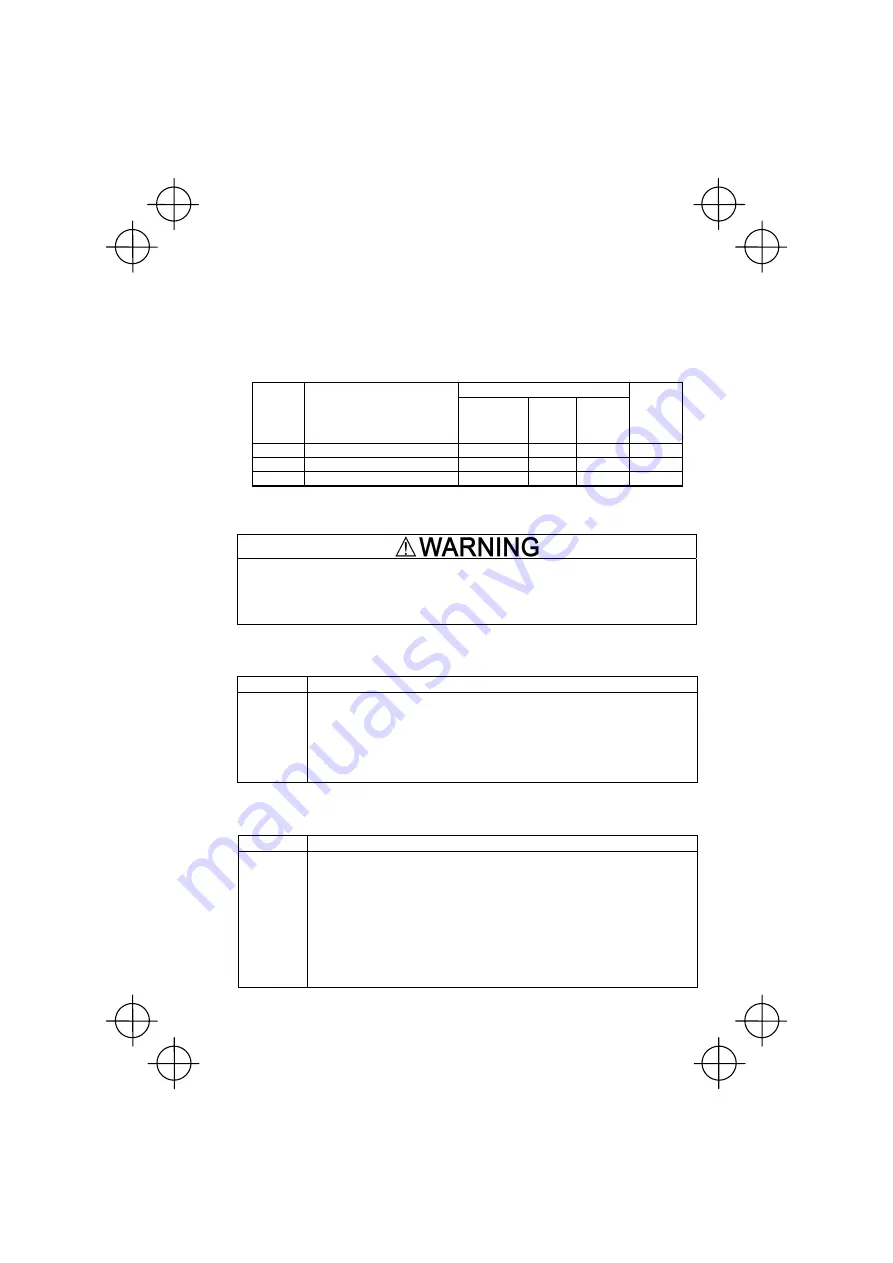
Table 8.1 lists alarm codes related to the PG interface card. For other alarm codes, refer to the 
FRENIC-Multi Instruction Manual (INR-SI47-1094-E), Chapter 6 "TROUBLESHOOTING." 

Table 8.1  Related Alarm Codes


Alarm for: 

Alarm 

code 

Alarm name 

Frequency 

control 

with pulse 

rate input 

Speed

control

Positioning

control 

Refer to 

Section: 

os 

Overspeed alarm 

NA 

NA 

8.1 

ere 

Excessive speed deviation alarm

NA 

NA 

8.2 

ero 

Positioning control alarm 

NA 

NA 

Y and C

8.3 

Y:  Always active. The protective function for the alarm is always active when the control is enabled. 

C:  Conditionally active. The protective function for the alarm is active when the control is enabled 

and the protective function is enabled with the function code. The factory default is "enabled." 

NA:  Not available when the control is enabled. 


If any of the protective functions has been activated, first remove the cause. Then, after 

checking that the all run commands are set to off, reset the alarm. Note that if the alarm is 

reset when any run command is set to on, the inverter may supply the power to the motor 

which may cause the motor to rotate. 

Injury may occur. 


8.1 Overspeed 

Alarm 

(

os

Table 8.2  Overspeed Alarm Specifications 

Alarm code 

Descriptions 

os 

• 

The inverter issues this alarm when the detected speed exceeds the 1.2 times the 

minimum value of either (1) or (2) below.


(1)


For the selected motor, 


Maximum frequency (F03 or A01) + Torque limiter (Frequency increment limit for 

braking, H76) 

(2) Frequency limiter, High (F15) 

• 

This protective function works when the inverter is outputting with the speed control 

with PG being enabled (F42 or A14 = 3 or 4 and 

PG/Hz

 is ON). 


8.2  Excessive Speed Deviation Alarm (

ere

Table 8.3    Excessive Speed Deviation Alarm Specifications 

Alarm code 

Descriptions 

ere


• 

This protective function recognizes a PG error by software based on the relationship 

between the speed command and the detected speed. 

  When the speed deviation between the speed command and the detected speed 

has exceeded the excessive speed deviation level specified by o17 during the period 

longer than the timer setting specified by o18, the protective function issues this 

alarm.


• 

This protective function provides two choices--"Stop running" (o19 = 1 or 2) and 

"Continue to run" (o19 = 0) when it is activated. When the latter is selected, the 

inverter continues to run with output to terminal [Y] without issuing an alarm. 

• 

This protective function works when the inverter is outputting with the speed control 

with PG being enabled (F42 or A14 = 3 or 4 and 

PG/Hz

 is ON). It does not, however, 

during DC braking or idling due to overload.


Содержание FRENIC-Multi Series

Страница 1: ...d before proceeding with installation connections wiring operation or maintenance and inspection Deliver this manual to the end user of this product Keep this manual in a safe place until this product...

Страница 2: ...produced or copied without prior written permission from Fuji Electric FA Components Systems Co Ltd All products and company names mentioned in this manual are trademarks or registered trademarks of t...

Страница 3: ...fe place Safety precautions Read this manual thoroughly before proceeding with installation connections wiring operation or maintenance and inspection Ensure you have sound knowledge of the device and...

Страница 4: ...nt appropriate measure to prevent the nearby sensors and devices from malfunctioning due to such noise Otherwise an accident could occur Operation Be sure to install the terminal cover before turning...

Страница 5: ...Icons The following icons are used throughout this manual This icon indicates information which if not heeded can result in the inverter not operating to full efficiency as well as information concern...

Страница 6: ...5 1 5 1 Specifications 5 1 5 2 Terminal Functions 5 1 5 3 Function Code List 5 1 5 4 Function Code Details 5 2 5 5 Description of the Control 5 3 5 5 1 Input pulse command polarity 5 3 5 5 2 Block di...

Страница 7: ...nterface card is applicable Table 1 1 Applicable ROM Version Series Type of inverter Applicable motor rating ROM version FRENIC Multi FRN E1 All capacities 0700 or later Checking the ROM version Use M...

Страница 8: ...o remove the terminal cover refer to the FRENIC Multi Instruction Manual INR SI47 1094 E Chapter 2 Section 2 3 Wiring 2 If the interface PCB is installed on the inverter push the hooks provided on bot...

Страница 9: ...ns of the PG 1 3 2 Mounting the PG to the motor The counterclockwise rotation when viewed from the motor output shaft is regarded as forward rotation see Figure 1 4 During rotation in the forward dire...

Страница 10: ...and referring to the connection diagrams given in Figures 2 1 to 2 3 1 Turn the inverter s power OFF 2 Use a shielded wire for wiring between the PG and the PG interface card 3 To prevent malfunction...

Страница 11: ...terminal for power supply and PG input XA A phase pulse input X XB B phase pulse input X XZ Z phase pulse input X Pulse input terminal for commands To supply speed commands from the pulse train gener...

Страница 12: ...M YA YB YZ PO PI CM Screw size M2 Tightening torque 0 22 to 0 25 N m Figure 1 8 Option Terminals Terminal PLC on the PG interface card cannot supply power to external equipment Use the terminal only f...

Страница 13: ...pulse rate input Figure 2 1 Connection Diagrams for Frequency Control with Pulse Rate Input Note 1 For details about applicable PG specifications refer to Table 1 2 in Chapter 1 Section 1 3 1 PG speci...

Страница 14: ...ols Figure 2 2 shows connection diagram examples for speed and positioning controls Figure 2 2 Connection Diagrams for Speed Control with PG and Positioning Control When using inverter internal power...

Страница 15: ...the Electromagnetic Compatibility EMC Directive connect the shielded cable to the ground of the inverter as shown below Figure 2 3 Connection Diagrams for Compliance with EMC Directive When using inve...

Страница 16: ...urthermore after powering the inverter ON but before starting inverter operation check the followings Check the wiring surely before running the inverter Incorrect wiring causes the inverter or other...

Страница 17: ...requency Control with Pulse Rate Input This control specifies a frequency command with pulse trains For details refer to Chapter 5 It can be used together with speed control with PG at the same time 4...

Страница 18: ...minal Receives power for the PG from an external source PO Power output terminal Outputs power to the PG CM Common terminal Common terminal for the PG power XA Command input terminal for A phase pulse...

Страница 19: ...me constant can stabilize the speed command in low pulse rate o07 o08 Command Pulse train input Pulse count factor 1 Command Pulse train input Pulse count factor 2 For the pulse input command these fu...

Страница 20: ...ity of the B Phase Pulse Input B phase input A phase input Polarity Figure 5 3 Polarity of the Run Forward Reverse Pulse Input Table 5 5 Relationship between Polarity of the Pulse Input FWD REV Comman...

Страница 21: ...ource PO Power output terminal Outputs power to the PG CM Common terminal Common terminal for the PG power YA Feedback input terminal for A phase pulse train Receives an A phase feedback pulse train Y...

Страница 22: ...pulse resolution 20 to 3600 P R 1024 N o10 Filter time constant 0 000 to 5 000 s 0 005 Y o11 Pulse count factor 1 1 to 9999 1 N o12 Feedback Input Pulse count factor 2 1 to 9999 1 N o13 Speed Control...

Страница 23: ...not exceed 35 00 in the ordinary system Modifying F03 A01 data requires readjustment of o02 and o03 data o04 Speed Control Filter time constant This function code specifies a time constant determinin...

Страница 24: ...Transmission ratio c d No of teeth b No of teeth a No of teeth a Radius c Radius Inverter FRN E1S PG U V W Figure 6 1 Speed Control Model Using a PG Pulse count factor 2 o12 Motor shaft speed Pulse c...

Страница 25: ...G from an external source PO Power output terminal Outputs power to the PG CM Common terminal Common terminal for the PG power XA Command input terminal for A phase pulse train Receives an A phase com...

Страница 26: ...999 to 999 p 0 Y J77 Preset point lower digits P 0 to 9999 1 p 0 Y J78 Creep speed switch point upper digits 0 to 999 p 0 Y J79 Creep speed switch point lower digits 0 to 9999 p 0 Y J80 Creep speed 0...

Страница 27: ...R J83 CP J85 Run command OFF Time ET J84 Timer output TO OFF Positioning completed PSET OFF Note The current position must be within E ER point after the time ET has elapsed Decl time F08 E11 Decl tim...

Страница 28: ...s the waiting time from when a run command comes ON with the S R terminal command being ON until the inverter starts running the motor This covers the delay of brake OFF If the output frequency has no...

Страница 29: ...he serial pulse input shares an input terminal with other functional pulse inputs when the positioning control is concurrently enabled with frequency control with pulse rate input and or speed control...

Страница 30: ...e S R being ON or A Z point correction is performed 7 5 Function Code Details o01 Command Feedback Input Input mode This function code switches the feedback pulse input mode with the data in the tens...

Страница 31: ...on the standard keypad Running status in Running mode on the multi function keypad Pulse count Upper 4 digits Lower 4 digits Remarks 9 999 999 999 9999 Maximum display value 19 999 1 9999 10 000 1 000...

Страница 32: ...ntrol completed PSET 8 Status where the positioning control is completed and the inverter is issuing PSET Stop position override alarm OT 9 Status where the inverter is issuing a stop position overrid...

Страница 33: ...rol Positioning control o01 Symbol X in the above table stands for PG terminals XA XB and XZ Specify their input modes with the data in the ones place of function code o01 Symbol Y stands for PG termi...

Страница 34: ...t t t 100 ms min Pulse train input Pulse train input 100 ms min For the pulse train input control restart pulse train input within 100 ms 100 ms max Pulse train input holding period Holds the pulse co...

Страница 35: ...the motor which may cause the motor to rotate Injury may occur 8 1 Overspeed Alarm os Table 8 2 Overspeed Alarm Specifications Alarm code Descriptions os The inverter issues this alarm when the detec...

Страница 36: ...larm PG ERR output 0 Continue to run None Active 1 Stop running Alarm mode 1 Any status of to in Figure 8 1 is kept exceeding the timer setting specified by o18 2 Stop running Alarm mode 2 Any status...

Страница 37: ...utput frequency and feedback position pulse when the inverter output frequency has exceeded the hysteresis width specified by E30 Frequency Arrival for 2 5 Hz min during the period longer than the tim...

Страница 38: ...MEMO...

Страница 39: ...n handling setting up and operating of the PG interface card Please feel free to send your comments regarding any errors or omissions you may have found or any suggestions you may have for generally i...

Страница 40: ...A Components Systems Co Ltd Mitsui Sumitomo Bank Ningyo cho Bldg 5 7 Nihonbashi Odemma cho Chuo ku Tokyo 103 0011 Japan Phone 81 3 5847 8011 Fax 81 3 5847 8172 URL http www fujielectric co jp fcs 2006...

Отзывы: