


7-8
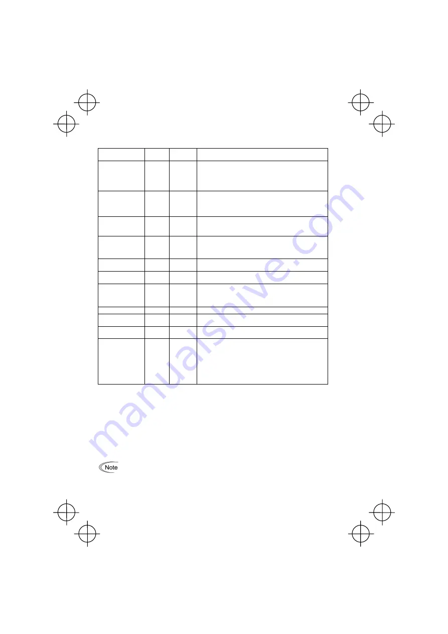
Table 7.11 Status Name and Number in Positioning Control
Positioning control
status
Status
name *1
Status
number *2
Descriptions
Positioning control
stopped
STOP 0 Status where
S
/
R
is OFF. Turning
S/R
ON shifts to "WAIT = 1"
where the inverter waits for a run command.
If the inverter output frequency is other than 0 Hz (Gate output)
when
S/R
is turned ON, it shifts to "RUN = 3" since the start
timer does not count.
Waiting for run
command
WAIT 1
Status
where
S
/
R
is ON and a run command is OFF.
Turning a run command ON in this status shifts to "ST = 2."
If the start timer (J73 data) is 0.0 s, the status shifts from "WAIT
= 1" to "RUN = 3."
Start timer counting
ST
2
Status where
S
/
R
and run command are ON and the start timer
is counting.
Upon completion of timer count, the status shifts to "RUN = 3."
Running RUN
3
Status until the inverter enters into a control zone "Current
position
≥
(E point - L point)" in forward operation or "Current
position
≤
(E point + L point)" in returning operation, or until Z
point correction occurs.
Z point correction
completed
Z 4
If Z point correction occurs in "RUN = 3," the inverter shifts to
this status.
Running in creep
speed
L 5
Status where the inverter is decelerating down to the creep
speed (J80) or is running at the creep speed.
Coasting CP
6
Status where the inverter is decelerating to a stop after
entering the control zone "Current position
≥
(E point - CP
point)" in forward operation or "Current position
≤
(E point + CP
point)" in returning operation.
End timer counting
ET
7
Status where the end timer is counting.
Positioning control
completed
PSET 8
Status where the positioning control is completed and the
inverter is issuing
PSET
.
Stop position
override alarm
OT 9
Status where the inverter is issuing a stop position override
alarm
OT
.
Stopped by
cancellation
CAN 10
If any inverter operation under positioning control is canceled
during any status of "ST = 2" to "ET = 7," the inverter enters
"CAN = 10." After that, the inverter turns the "Timer output"
TO
OFF and issues the "Positioning completed"
PSET
or "Stop
position override alarm"
OT
.
Once the inverter enters "CAN = 10", the inverter remains in
this status and keeps the reference frequency at 0 Hz as long
as the run command is not turned OFF.
*1
The status name can be displayed in "Drive Monitoring" menu on the LCD monitor of the
multi-function keypad.
*2
The status number can be displayed in Menu #3 "Drive Monitoring," Display item 3_20 on the
standard keypad or on the LCD monitor of the multi-function keypad.
7.7 Serial Pulse Receiving Function
When the
S
/
R
terminal command is assigned to any digital input terminals [X]s and the serial pulse
receiving function is enabled, the pulse train input from host equipment can specify the stop position
(E point). Function codes J81 and J82 (Stop position) save the input pulse count.
Function code J86 specifies the pulse input mode for the serial pulse train input.
When the serial pulse receiving input shares an input terminal with other function input
(e.g. Section 7.8), the inverter counts the PG input pulse train as the serial pulse
receiving input for E point pulse count only when
SPRM
is ON. On the contrary, if the
serial pulse receiving input terminal is exclusively assigned, the inverter counts the input
for E point data independently the ON/OFF status of
SPRM
.
Содержание FRENIC-Multi Series
Страница 38: ...MEMO...


