


Page
9
of
28
Fuji Electric Europe GmbH
5. Connections
5.1 Control signals connection
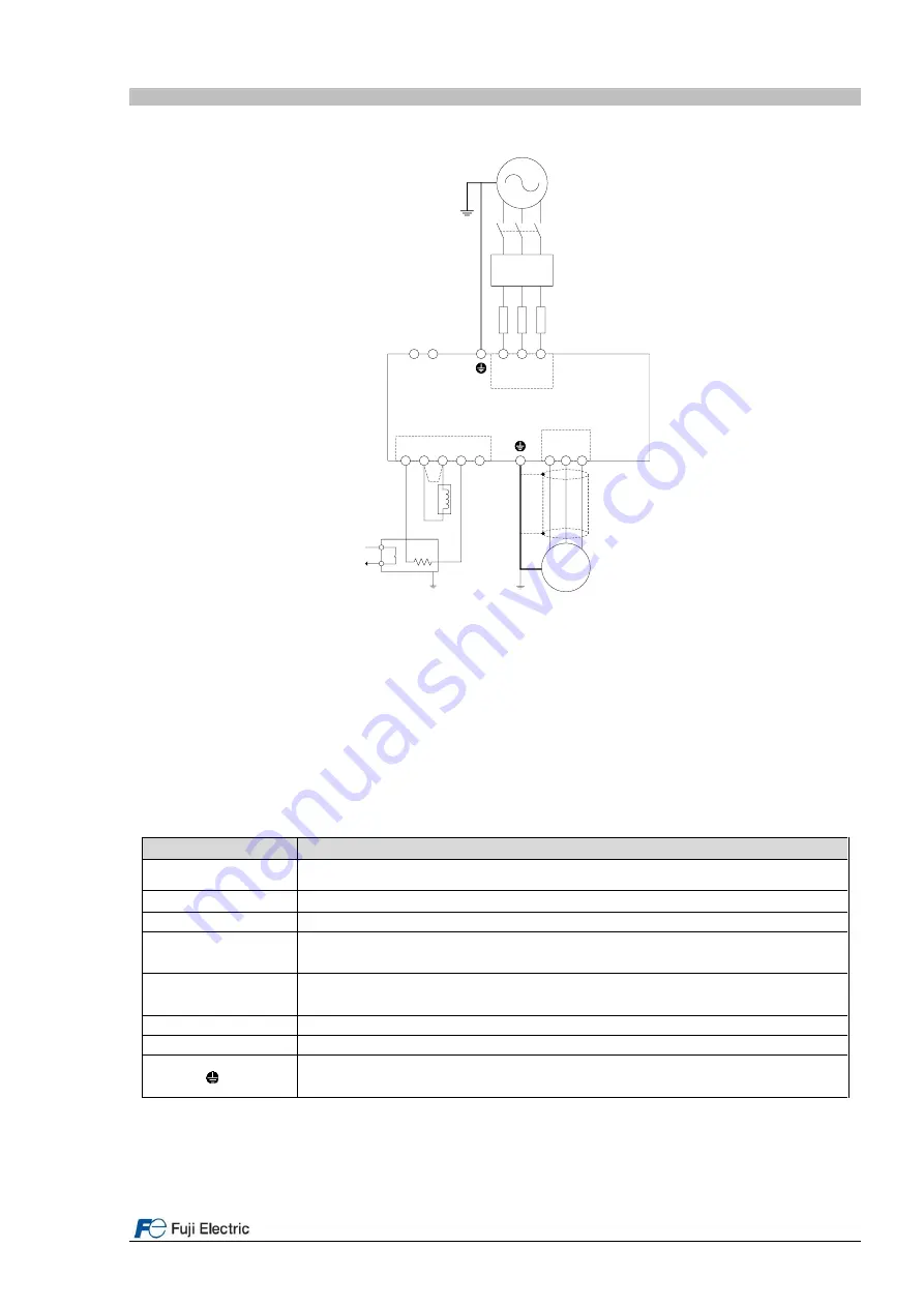
FRENIC-Lift (LM2)
DCRE4-x.x-J
(DC react or)
(THR)
(PLC)
U
V
W
MOTOR
EMC
G
PEN
P2
N(-)
DB
P3
P(+)
G
M
*1
*2
*3
*4
*6
*6
BRE-xxRxxxxW
(braking resistor)
L1/R L2/S L3/T
Input
EMC filter
Figure 5.1. Power terminals connection.
Note *1: Not used.
Note *2: DC Reactor terminals:
-
In case of NOT installing DC Reactor wire a jumper between terminals P2 and P3.
Note *3: Use the metal plates placed on removable terminals to connect the shield by means of metal cable ties for
example.
Note *4: In case of not installing the two MC between motor and inverter, please follow the procedure explained in
“
AN-Lift2-0001
”
document.
All the power terminals, independently of frame, even do not appear on figure 5.1 and 5.2 are listed in table 5.1.
Table 5.1. Power terminals description.
Terminal label
Description of the power terminals
L1/R, L2/S, L3/T
3-phase supply input from mains supply.
U, V, W
3-phase motor connection for induction motors.
U0, V0, W0
Not used.
P2, P3
DC Reactor connection.
24V+, 24V-
Input power terminals for 24 VDC. These terminals have to be used in case of rescue
operation by means of batteries to supply control circuit.
DB , P(+)
Connection of external braking resistor.
EMC
Not used.
G
Terminals for the connection of the inverter enclosure with the protecting earth.
3 terminals available.
Please connect the screen in both motor and inverter sides. Ensure that the screen is continued also through the
main contactors (if used).
It is recommended to use braking resistors with thermal switch in order to protect the system from failures.
Additionally, inverter has a software function to electronically protect the system (For additional information please
check parameters F50 to F52).


