


86
3
Selection and application
3-16 Ground fault protection in system applications
Note: The number of ground fault protection devices can be reduced once
potential equalization work and fault loop impedance calculations are
completed with TN systems, but never install low-voltage electrical
equipment using both TN and TT systems together in the same location.
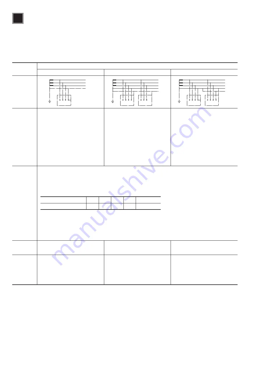
Table 3-31 Comparison of grounding system (TN, TT and IT systems) characteristics and precautions for their use
Comparison
item
Wiring system
TN-C
TN-S
TN-C-S
Circuit
diagram
L
1
L
2
L
3
PEN
L
1
L
2
L
3
N
PE
L
1
L
2
L
3
PE
N
Features
s4HENEUTRALCONDUCTORANDPROTECTIVE
conductor functions for the overall
system are combined into a single
conductor.
s!LLEXPOSEDCONDUCTIVEPARTSOFTHE
equipment are connected to a PEN
conductor.
s#ALCULATETHEFAULTLOOPIMPEDANCEFOR
shock protection and use an MCCB for
system protection.
s7IDELYUSEDIN&RAANDTHE
United States
s4HENEUTRALCONDUCTORANDPROTECTIVE
conductor for the overall wiring system
are completely separate.
s4HEPROTECTIVECONDUCTOR0% ISEITHERA
metal sheath on the supply cable for the
equipment or a conductor completely
separate from the system.
s!LLEXPOSEDCONDUCTIVEPARTSOFTHE
equipment are connected to the
conductor through the main ground
terminal on the equipment.
s4HENEUTRALCONDUCTORANDPROTECTIVE
conductor functions for part of the wiring
system are combined into a single
conductor.
s4HEMOSTCOMMONCONlGURATIONSARE
the TN-C wiring system on the power
supply side and a TN-S wiring system
on the equipment side.
s!LLEXPOSEDCONDUCTIVEPARTSOF
the equipment are connected to a
conductor through the main ground
terminal and the neutral line terminal
on the equipment, which are connected
together.
Indirect
contact
protection
standards
From the phase conductor to the ground for the exposed parts of the load equipment: Contact voltage of 50V max.
Zero impedance short-circuiting from the phase conductor in the equipment to the protective conductor or exposed parts:
U
0
t
la × Zs where U0 is the nominal voltage to ground (effective AC value), Ia is the maximum breaking time from the following
table as a function of U0 or the current that causes the protective device to trip automatically within the conditional time setting
of five seconds, and Zs is the fault loop impedance derived from the charging conductor from the power supply to the fault point
and the protective conductor between the fault point and the power supply.
s-AXIMUMBREAKINGTIMEFORA4.SYSTEM
U
0
(V)
120
230
277
400
400 or higher
Maximum breaking time (s)
0.8
0.4
0.4
0.2
0.1
s#ONDITIONSFORAMAXIMUMBREAKINGTIMEOFS4HEMAXIMUMBREAKINGTIMEINTHETABLEABOVEMAYBEEXCEEDEDINBRANCH
circuits that supply power to stationary equipment only, but 5 s or less is the allowable breaking time. Supplemental conditions
must be provided separately if other branch circuits that require the maximum breaking time given in the table are connected to
those branch circuits.
MCCB
s7ITHINVERSETIMEDELAYCHARACTERISTICS)AISTHECURRENTTHATCANTRIPTHE-##"AUTOMATICALLYWITHINS
s7ITHINSTANTANEOUSTRIPPINGCHARACTERISTICS)AISTHESMALLESTCURRENTTHATCANTRIPTHE-##"AUTOMATICALLY
Applicable
protective
device
s-##"
s-##"
s%,#"
s-##"
s%,#"APPLICABLEONLYIN4.3WIRING
circuits only)
Application
(design)
precautions
1. Use only MCCBs.
2. Calculate the fault loop impedance.
3. Ignore the fault point impedance
between the phase conductor and the
protective conductor.
1. Select a suitable ground fault
protection device for the protection
system.
2. Overcurrent breaking precautions:
Same as TN-C items 2 and 3.
1. Select a suitable ground fault
protection device for the protection
system.
2. ELCBs can only be installed in certain
locations.
3. Overcurrent breaking precautions:
Same as TN-C items 2 and 3.