Fronius TransTig 1700 Скачать руководство пользователя страница 65

2

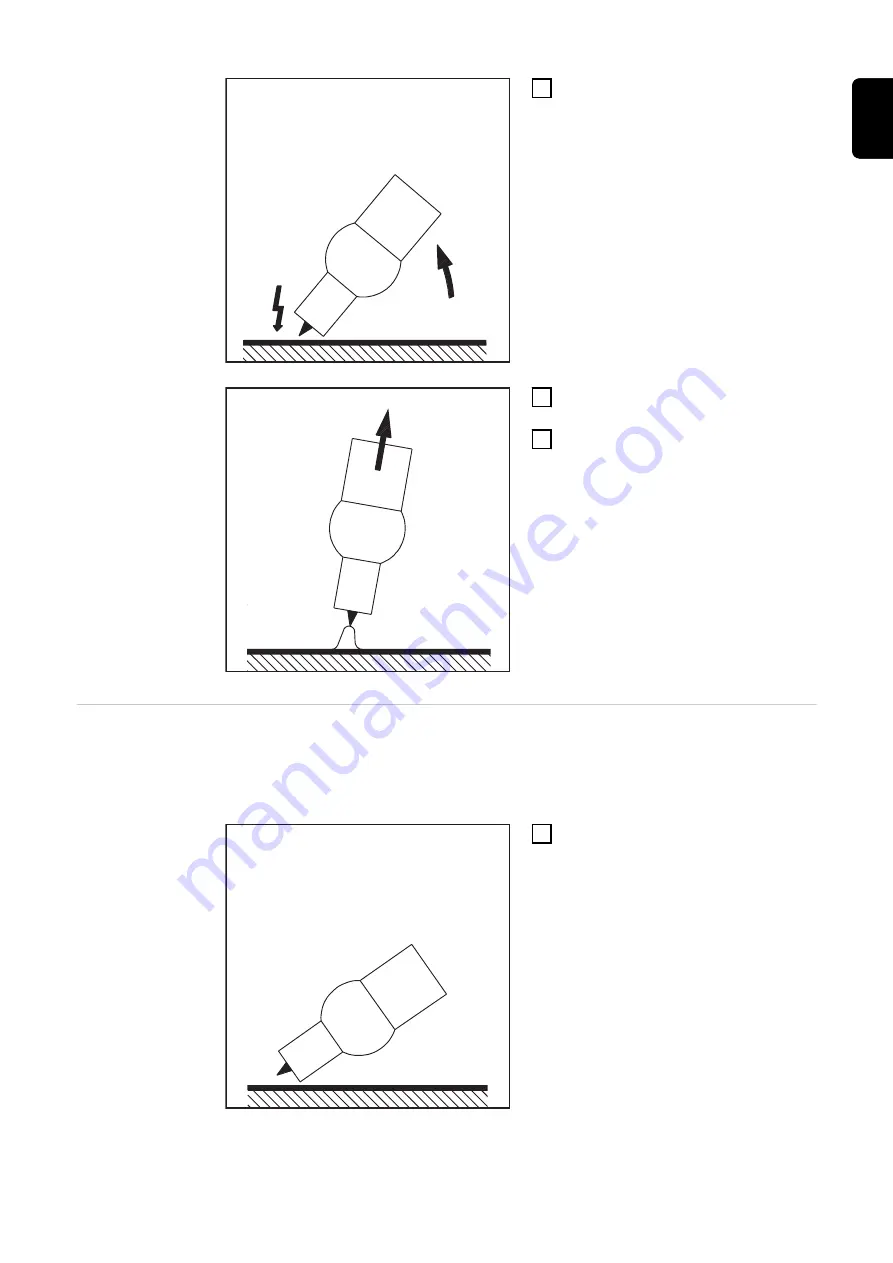
Increase the tilt angle of the torch
and actuate the torch trigger ac-
cording to the mode you have se-
lected

The arc ignites without the electrode
touching down on the workpiece.

3

Tilt the torch back into the normal
position

4

Carry out welding

Touchdown igni-
tion

If the HFt setup parameter is set to OFF, HF ignition is deactivated. The welding
arc is ignited by touching the workpiece with the tungsten electrode.

Procedure for igniting the arc using touchdown ignition:

1

Place the gas nozzle down on the
ignition location so that there is a
gap of approx. 2 to 3 mm (5/64 to
1/8 in.) between the tungsten elec-
trode and the workpiece

65

EN

Содержание TransTig 1700

Страница 1: ...perating Instructions TransTig 800 TransTig 2200 TransTig 2500 3000 TransTig 4000 5000 MagicWave 1700 2200 MagicWave 2500 3000 MagicWave 4000 5000 42 0426 0027 EN 023 21092022 EN Operating instruction...

Страница 2: ......

Страница 3: ...15 Safety measures in normal operation 16 Commissioning maintenance and repair 16 Safety inspection 17 Disposal 17 Safety symbols 17 Data protection 17 Copyright 18 General information 19 General 21...

Страница 4: ...Connecting the gas cylinder 53 Establishing a ground earth connection to the workpiece 54 Connecting the welding torch 54 Welding 55 TIG modes 57 Safety 57 Symbols and their explanations 57 2 step mo...

Страница 5: ...level 2 84 Troubleshooting and maintenance 87 Troubleshooting 89 General 89 Safety 89 Displayed service codes 89 Power source troubleshooting 92 Care maintenance and disposal 94 General 94 Safety 94...

Страница 6: ...8 TransTig 4000 MV 119 TransTig 5000 MV 120 Explanation of footnotes 121 Terms and abbreviations used 122 General 122 Terms and abbreviations A F 122 Terms and abbreviations G H 122 Terms and abbrevia...

Страница 7: ...pany inefficient operation of the device All persons involved in commissioning operating maintaining and servicing the device must be suitably qualified have sufficient knowledge of welding and read a...

Страница 8: ...not be held liable for any damage arising from such usage Ambient temperature range during operation 10 C to 40 C 14 F to 104 F during transport and storage 20 C to 55 C 4 F to 131 F Relative humidity...

Страница 9: ...urrent Greater noise pollution Harmful welding fumes and gases Suitable protective clothing must be worn when working with the device The protective clothing must have the following properties Flame r...

Страница 10: ...and gases Fumes and hazardous gases must not be breathed in must be extracted from the working area using appropriate methods Ensure an adequate supply of fresh air Ensure that there is a ventilation...

Страница 11: ...base or cover must extend over the entire area between the body and the earth or ground potential All cables and leads must be secured undamaged insulated and adequately di mensioned Replace loose con...

Страница 12: ...ents such as insulation against conductive floor or insulation to conductive racks If power distribution boards twin head mounts etc are being used note the fol lowing The electrode of the welding tor...

Страница 13: ...elds may pose as yet unknown risks to health Effects on the health of persons in the vicinity e g those with pacemakers and hearing aids Individuals with pacemakers must seek advice from their doctor...

Страница 14: ...G and TIG devices If the wirefeeder is attached to a crane holder during welding always use a suit able insulated wirefeeder hoisting attachment MIG MAG and TIG devices If the device has a carrying st...

Страница 15: ...pe of shielding gas Shielding gas is colourless and odourless and in the event of a leak can displace the oxygen in the ambient air Ensure an adequate supply of fresh air with a ventilation rate of at...

Страница 16: ...ve it beforehand if the device is to be transported by crane Only the manufacturer s original coolant is suitable for use with our devices due to its properties electrical conductibility anti freeze a...

Страница 17: ...n can be obtained from your service centre They will provide you on request with any documents you may re quire Disposal Do not dispose of this device with normal domestic waste To comply with the Eur...

Страница 18: ...time of printing We reserve the right to make changes The contents of the operating instructions shall not provide the basis for any claims whatsoever on the part of the pur chaser If you have any su...

Страница 19: ...General information 19...

Страница 20: ...20...

Страница 21: ...al sys tem add ons e g JobMaster TIG welding torches robot welding torches remote control units etc Automatic cap shaping for AC weld ing with MagicWave power sources takes the diameter of the tungste...

Страница 22: ...to any changes Control algorithms ensure that the desired target state is maintained This results in a precise welding process exact reproducibility of all results excellent weld properties Applicati...

Страница 23: ...he device US power sources come with extra warning notices affixed to the device The warning notices must NOT be removed or painted over US version of power source with additional warning notices e g...

Страница 24: ...Description 1 Power sources 2 Cooling units 3 Trolley with gas cylinder holder 4 Pedal remote control unit 5 TIG welding torch Standard Up Down 6 JobMaster TIG welding torch JobMaster TIG welding torc...

Страница 25: ...Control elements and connections 25...

Страница 26: ...26...

Страница 27: ...that are not described in these operating instructions or vice versa Individual illustrations may also differ slightly from the actual controls on your device but these controls function in exactly t...

Страница 28: ...f the following sections MagicWave control panel TransTig control panel Key combinations special functions 1 3 2 4 6 5 MagicWave control panels TransTig control panels 1 MW 1700 2200 4 TT 2200 2 MW 25...

Страница 29: ...value reached by the main current I1 As soon as any other welding parameter is selected the Hold indic ator goes off The Hold values will continue to be available however if welding parameter I1 is se...

Страница 30: ...nd HCU setup parameters have been selected s indicator lights up when the tup and tdown welding parameters plus the following setup parameters have been selected GPr G L G H UPS tAC Hti HFt mm indicat...

Страница 31: ...ing parameters to be used when welding The sequence of welding para meters follows a clothesline structure Use the left and right welding parameter selection buttons to navigate within the welding par...

Страница 32: ...ted The left hand digital display shows the actual welding current value In the welding parameters overview 10 LEDs for the various paramet ers IS t1 etc light up to show the relevant position in the...

Страница 33: ...No Function IMPORTANT The functions available on the control panel of system components are restricted in the same way as those on the control pan el of the power source 33 EN...

Страница 34: ...alue reached by the main current I1 As soon as any other welding parameter is selected the Hold indic ator goes off The Hold values will continue to be available however if welding parameter I1 is sel...

Страница 35: ...cted s indicator lights up when the tup and tdown welding parameters plus the following setup parameters have been selected GPr G L G H UPS tAC Hti HFt mm indicator lights up when the Fdb setup parame...

Страница 36: ...welding para meters Starting current Is for TIG welding The starting current IS is saved separately for the TIG AC welding and TIG DC welding modes Main current I1 welding current for TIG welding for...

Страница 37: ...for selecting welding parameters within the welding parameters over view 9 When a welding parameter is selected the LED on the relevant para meter symbol lights up 13 HF high frequency ignition indica...

Страница 38: ...n The operating time records the actual arc burning time since starting for the first time For example 654 32 1 65 432 1 hours 65 432 hours 6 mins IMPORTANT The operating time display is not suitable...

Страница 39: ...ction standardised connection socket for system add ons e g remote control JobMaster TIG welding torch etc 3 Handle only for MagicWave 2200 carrying strap for MagicWave 1700 4 Torch control connection...

Страница 40: ...tion socket for system add ons e g remote control JobMaster TIG welding torch etc 3 Handle 4 Torch control connection for connecting the control plug of a conventional welding torch 5 Welding torch co...

Страница 41: ...the electrode cable for manual metal arc welding 4 Torch control connection for connecting the control plug of a conventional welding torch 5 LocalNet connection standardised connection socket for sy...

Страница 42: ...ion standardised connection socket for system add ons e g remote control JobMaster TIG welding torch etc 3 Handle 4 Torch control connection for connecting the control plug of a conventional welding t...

Страница 43: ...ction standardised connection socket for system add ons e g remote control JobMaster TIG welding torch etc 3 Handle 4 Torch control connection for connecting the control plug of a conventional welding...

Страница 44: ...ction socket for system add ons e g remote control JobMaster TIG welding torch etc 3 Torch control connection for connecting the control plug of a conventional welding torch 4 current socket with bayo...

Страница 45: ...Installation and commissioning 45...

Страница 46: ...46...

Страница 47: ...described TIG AC welding MagicWave power source Grounding earthing cable TIG welding torch with rocker switch Gas connection shielding gas supply with pressure regulator Filler metals as required by...

Страница 48: ...ons The device is tested to IP 23 protection meaning Protection against penetration by solid foreign bodies with diameters 12 5 mm 0 49 in Protection against spraywater at any angle up to 60 to the ve...

Страница 49: ...erator powered opera tion MW 1700 2200 TT 2200 The MW 1700 2200 and TT 2200 power sources are generator compatible provided that the maximum apparent power delivered by the generator is at least 10 kV...

Страница 50: ...WG 6 AWG American Wire Gauge Safety WARNING Danger due to work that has been carried out incorrectly This can result in serious injury and damage to property The work described below must only be carr...

Страница 51: ...screws 2 x and clamping nut size 30 on the strain relief device PE W1 V1 U1 5 7 8 6 5 Insert the mains cable into the strain relief device NOTE Push the mains cable in far enough to make it possible...

Страница 52: ...he hexagon nut size 50 mm into the holding plate NOTE To ensure a reliable earth connection to the housing of the power source the points on the hexagon nut must be facing the holding plate 6 Screw th...

Страница 53: ...gher power ranges The cooling unit is powered from the power source The cooling unit is ready for operation when the mains switch of the power source is in the I position More information on the cooli...

Страница 54: ...r TransTig in the current socket 3 Use the other end of the grounding earthing cable to establish a connection to the workpiece Connecting the welding torch CAUTION Risk of damage from high frequencie...

Страница 55: ...Welding 55...

Страница 56: ...56...

Страница 57: ...rch trigger GPr Gas pre flow time SPt Spot welding time IS Starting current phase the temper ature is raised gently at low welding current so that the filler metal can be positioned correctly IE Final...

Страница 58: ...e torch trig ger Welding with main current I1 Release the torch trigger Lowering to final current IE Pull back and hold the torch trigger End of welding Release the torch trigger I t I1 GPr IS t S P U...

Страница 59: ...he welding current will rise at the specified upslope value from the starting current IS until it reaches the main current value I1 Push forward and hold the torch trigger for intermediate lowering Re...

Страница 60: ...eal cap for the specified diameter of the tungsten elec trode is formed during welding start up A separate cap shaping opera tion on a test workpiece is not necessary The automatic cap shaping functio...

Страница 61: ...ake sure that the power source mains switch is in the O position Before carrying out any work on the device make sure that the power source is unplugged from the mains Welding para meters Starting cur...

Страница 62: ...ower Electrode diameter Unit mm in Setting range OFF max OFF max Factory setting 2 4 0 095 Preparation 1 Plug in the mains plug CAUTION Risk of injury and damage from electric shock As soon as the mai...

Страница 63: ...stored until the next time they are changed This applies even if the power source is switched off and on again in the meantime 5 Open the gas cylinder valve 6 Set the shielding gas flow rate Press th...

Страница 64: ...se prescribed protective clothing especially gloves Only use suitable completely intact and undamaged TIG hosepacks Do not work in damp or wet environments Take special care when working on scaffoldin...

Страница 65: ...osition 4 Carry out welding Touchdown igni tion If the HFt setup parameter is set to OFF HF ignition is deactivated The welding arc is ignited by touching the workpiece with the tungsten electrode Pro...

Страница 66: ...e touches the workpiece 4 Raise the welding torch and move it into its normal position The arc ignites 5 Carry out welding End of welding 1 Depending on the set mode finish welding by releasing the to...

Страница 67: ...e specified in the set up menu the power source cuts out automatically The service code no IGn appears on the control panel To try again press any key on the control panel or press the torch trigger T...

Страница 68: ...meters as a function of the pre set main current I1 The pulsed welding current begins after the end of the starting current phase IS with the upslope phase UPS Depending on what tAC time has been set...

Страница 69: ...on 1 Switch off cooling units set setup parameter C C to OFF 2 Move the mains switch to the O position 3 Disconnect the mains plug 4 Remove the TIG welding torch 5 Plug the grounding cable in and latc...

Страница 70: ...pposite cur rent sockets i e swap them over d Plug in the mains plug CAUTION Risk of injury and damage from electric shock As soon as the mains switch is in the I position the rod electrode in the ele...

Страница 71: ...tart current HCU must be 100 Settings examples HCU 100 The HotStart current corresponds to the set welding current I1 The hotstart function is not activated HCU 170 The HotStart current is 70 higher t...

Страница 72: ...72...

Страница 73: ...Setup settings 73...

Страница 74: ...74...

Страница 75: ...et up menu Set up parameters that have an immediate effect on the welding process Set up parameters needed for making the preliminary settings on the weld ing system The welding parameters are arrange...

Страница 76: ...right parameter selection button to select the welding parameter that you want to change 2 Use the adjusting dial to change the welding parameter value Exiting the set up menu 1 Press the Mode button...

Страница 77: ...aximum etc If Aut is set the gas post flow time G H is calculated automatically Imin Imax I t G H G L 1 2 Legend 1 Gas post flow time at any given moment 2 Welding current at any given moment Gas post...

Страница 78: ...set up menu 1 Press the Mode button Welding para meters in the TIG setup menu Minimum and maximum are used for setting ranges that differ according to power source wirefeeder welding program etc tAC...

Страница 79: ...0 9 9 Factory setting 0 1 Eld TransTig only Electrode diameter Unit mm in Setting range 0 max 0 max Factory setting 2 4 0 1 HFt High frequency time high frequency ignition Time interval between the H...

Страница 80: ...e welding arc is ignited I 2 Reduced current Intermediate lowering of the welding current in order to prevent any local overheating of the base material 4 step mode Unit of main current I1 Setting ran...

Страница 81: ...5 Factory setting 0 IMPORTANT Before phase adjustment the ACF parameter must be set to Syn in the AC polarity reversal Setup menu Phase adjustment takes place as follows Prepare a test workpiece for s...

Страница 82: ...r value Exiting the set up menu 1 Press the Mode button Welding para meters in the rod electrode set up menu Minimum and maximum are used for setting ranges that differ according to power source wire...

Страница 83: ...into the weld pool this measure prevents the weld pool solidifying as well as preventing more prolonged short circuiting of the arc This largely prevents the rod electrode from sticking FAC Factory R...

Страница 84: ...ing parameters 1 Use the left or right parameter selection button to select the welding parameter that you want to change 2 Use the adjusting dial to change the welding parameter value Exiting the rod...

Страница 85: ...ective of the welding voltage This results in a vertical characteristic 4 The con parameter is especially suitable for rutile electrodes and basic electrodes as well as for arc air gouging For arc air...

Страница 86: ...c force dynamic 50 The characteristics 4 5 and 6 shown here apply when using a rod electrode whose characteristic corresponds to the load line 1 at a given arc length Depending on what welding current...

Страница 87: ...Troubleshooting and maintenance 87...

Страница 88: ...88...

Страница 89: ...ource mains switch to the O position Disconnect the power source from the grid Ensure that the power source remains disconnected from the mains until all work has been completed After opening the devi...

Страница 90: ...cool down Cause Remedy tP6 xxx Note xxx stands for a temperature value Overtemperature in the primary circuit of the power source Allow power source to cool down Cause Remedy tS1 xxx Note xxx stands f...

Страница 91: ...ut out of the power source Switch off the power source wait for 10 seconds and then switch it on again If you have tried this several times and the error keeps re curring contact After Sales Service C...

Страница 92: ...k the mains lead ensure that the mains plug is plugged in Mains socket or mains plug faulty Replace faulty parts Mains fuse protection Change the mains fuse protection Cause Remedy Cause Remedy Cause...

Страница 93: ...ervice Cause Remedy Cause Remedy Cause Remedy Cause Remedy Cause Remedy Poor weld properties Incorrect welding parameters Check the settings Grounding earthing connection is incorrect Check the ground...

Страница 94: ...n the power source mains switch to the O position Disconnect the power source from the grid Ensure that the power source remains disconnected from the mains until all work has been completed After ope...

Страница 95: ...e with dry reduced compressed air 2 If a lot of dust has accumulated clean the cooling air ducts WARNING An electric shock can be fatal Risk of electric shock from improperly connected ground cables a...

Страница 96: ...96...

Страница 97: ...Appendix 97...

Страница 98: ...98...

Страница 99: ...mption at a wire speed of 10 m min 1 0 mm wire electrode dia meter 1 2 mm wire electrode dia meter 1 6 mm wire electrode dia meter Steel wire electrode 3 7 kg h 5 3 kg h 9 5 kg h Aluminium wire electr...

Страница 100: ...nsists of 8 digits for example 28020099 The first two digits give the number from which the year of production of the device can be calculated This figure minus 11 gives the year of production For exa...

Страница 101: ...k of conformity S CE MagicWave 2200 Mains voltage 230 V Mains voltage tolerance 20 15 Grid frequency 50 60 Hz Mains fuse protection slow blow 16 A Mains connection1 No restrictions Primary continuous...

Страница 102: ...rce efficiency at 180 A 27 2 V 81 MagicWave 2500 Mains voltage 3 x 400 V Mains voltage tolerance 15 Grid frequency 50 60 Hz Mains fuse protection slow blow 16 A Mains connection1 Zmax on PCC3 122 mOhm...

Страница 103: ...s fuse protection slow blow 16 A Mains connection1 Zmax on PCC3 87 mOhm Primary continuous power 100 D C 2 5 5 kVA Cos phi 0 99 Welding current range TIG 3 300 A Electrode 10 300 A Welding current at...

Страница 104: ...0 240 V 1 x 200 240 V 16 A 32 A 32 A Mains connection1 Zmax on PCC3 122 mOhm Primary continuous power 100 D C 2 3 x 400 460 V 3 x 200 240 V 1 x 200 240 V 4 8 kVA 4 4 kVA 3 9 kVA Cos phi 0 99 Welding c...

Страница 105: ...EN IEC 60974 10 A Dimensions L W H with handle 560 250 435 m m 22 0 9 8 17 1 in Weight 28 2 kg 62 17 lb Mark of conformity S CE Idle state power consumption at 400 V 46 5 W Power source efficiency at...

Страница 106: ...0 min 40 C 104 F 40 D C 2 10 min 40 C 104 F 50 D C 2 220 A 10 min 40 C 104 F 100 D C 2 160 A Open circuit voltage 89 V Working voltage TIG 10 1 22 0 V Electrode 20 4 32 0 V Striking voltage Up 10 kV T...

Страница 107: ...ltage 90 V Working voltage TIG 10 1 26 0 V Electrode 20 4 36 0 V Striking voltage Up 9 5 kV The arc striking voltage is suitable for manual operation Degree of protection IP 23 Type of cooling AF Insu...

Страница 108: ...rc striking voltage is suitable for manual operation Degree of protection IP 23 Type of cooling AF Insulation class F EMC device class in accordance with EN IEC 60974 10 A Dimensions L W H with handle...

Страница 109: ...Degree of protection IP 23 Type of cooling AF Insulation class F EMC device class in accordance with EN IEC 60974 10 A Dimensions L W H with handle 625 290 705 m m 24 6 11 4 27 8 i n Weight 60 kg 132...

Страница 110: ...on IP 23 Type of cooling AF Insulation class F EMC device class in accordance with EN IEC 60974 10 A Dimensions L W H with handle 625 290 705 m m 24 6 11 4 27 8 i n Weight 60 kg 132 30 lb Mark of conf...

Страница 111: ...of cooling AF Insulation class B EMC device class in accordance with EN IEC 60974 10 A Dimensions L W H with handle 485 180 344 m m 19 1 7 1 13 5 in Weight without handle 14 2 kg 31 3 lb Weight with h...

Страница 112: ...e of cooling AF Insulation class B EMC device class in accordance with EN IEC 60974 10 A Dimensions L W H with handle 485 180 390 m m 19 1 7 1 15 4 in Weight without handle 16 4 kg 37 lb Weight with h...

Страница 113: ...F Insulation class B EMC device class in accordance with EN IEC 60974 10 A Dimensions L W H with handle 560 250 435 m m 22 0 9 8 17 1 in Weight 24 2 kg 53 35 lb Mark of conformity S CE Idle state powe...

Страница 114: ...rdance with EN IEC 60974 10 A Dimensions L W H with handle 560 250 435 m m 22 0 9 8 17 1 in Weight 24 2 kg 53 35 lb Mark of conformity S CE Idle state power consumption at 400 V 45 2 W Power source ef...

Страница 115: ...t 1 x 200 240 V 10 min 40 C 104 F 50 D C 2 220 A 10 min 40 C 104 F 55 D C 2 10 min 40 C 104 F 100 D C 2 190 A Open circuit voltage 85 V Working voltage TIG 10 1 20 0 V Electrode 20 4 30 0 V Striking v...

Страница 116: ...300 A Welding current range single phase TIG 3 220 A Electrode 10 180 A Welding current at 3 x 400 460 V 10 min 40 C 104 F 45 D C 2 300 A 10 min 40 C 104 F 50 D C 2 10 min 40 C 104 F 100 D C 2 240 A W...

Страница 117: ...requency 50 60 Hz Mains fuse protection slow blow 35 A Mains connection1 Restrictions pos sible Primary continuous power 100 D C 2 11 8 kVA Cos phi 0 99 Welding current range TIG 3 400 A Electrode 10...

Страница 118: ...ns connection1 Restrictions pos sible Primary continuous power 100 D C 2 15 1 kVA Cos phi 0 99 Welding current range TIG 3 500 A Electrode 10 500 A Welding current at 10 min 40 C 104 F 40 D C 2 500 A...

Страница 119: ...estrictions pos sible Primary continuous power 100 D C 2 11 5 kVA Cos phi 0 99 Welding current range TIG 3 400 A Electrode 10 400 A Welding current at 10 min 40 C 104 F 40 D C 2 10 min 40 C 104 F 45 D...

Страница 120: ...1 Restrictions pos sible Primary continuous power 100 D C 2 14 2 kVA Cos phi 0 99 Welding current range TIG 3 500 A Electrode 10 500 A Welding current at 10 min 40 C 104 F 40 D C 2 500 A 10 min 40 C 1...

Страница 121: ...V 89 Explanation of footnotes 1 connected to public mains supply with 230 400 V and 50 Hz 2 D C Duty cycle 3 PCC interface to the public grid 4 TIG welding 5 MMA welding 6 An emission class A device i...

Страница 122: ...g parameters in CMT job correction or arc force dynamic and pulse correction settings in the set up menu for the Stand ard control panel Eld Electrode diameter When Eld is selected for the external pa...

Страница 123: ...rmediate lowering PhA Phase Adjustment Phase adjustment of the mains connection of two power sources for simultan eous AC welding Pri Pre Ignition delayed high frequency ignition tAC Tacking function...

Страница 124: ......

Отзывы: