background image

13

1. Fit the feed line 

below

 the shaft seal.

2. Fit the drain line 

above

 the shaft seal.

6.9

Cleaning

Only use cleaning agents that meet the technical hygiene stan-
dards for the respective pumped medium.

1. Before closing the pump, make sure that there are no for-

eign substances inside the pump and pipelines.

2. Close the pump.

3. Connect the pipelines.

4. Prior to first use, clean the pump and pipeline system com-

pletely.

7

Operation

7.1

Safety notices

Closed valve in the pressure line 

Serious personal injury and property damage caused by a 
bursting of the system due to very high pressure build-up.

Both before switching on and during operation, make sure 
that all of the pressure line’s valves are open. 

Provide a bypass or other approved safety devices for pres-
sure peaks, as this is a positive displacement pump. 

Closed valve in the suction line 

Damage to the shaft seal due to dry running of the pump.

Both before switching on and during operation, make sure 
that all of the suction line’s valves are open. 

No pumped medium inside the pump

Dry running of the pump. Damage to the shaft seal.

For single shaft seal pumps, make sure that there is always 
pumped medium inside the pump both prior to and during 
operation.

7.2

Commence operation

Double shaft seal: 

Loss of barrier fluid

Damage to the shaft seal.

During operation, make sure that: 

– Barrier fluid with sufficient pressure is flowing through 

the double shaft seal (see information on the enclosed 

“Data sheet”

),

– The temperature of the barrier fluid is maintained at T < 

70°C. 

1. Open the valve in the suction line. 

2. Open the valve in the pressure line. 

3. Fill the pump and suction line with pumped medium to the 

upper edge of the pump. Allow any air pockets that may be 
present to escape. 

4. Only for pumps with barrier or quench fluid: 

Verify the necessary barrier pressure. For maximum barrier 
pressure, please refer to the 

“Data sheet”

in the enclosed do-

cuments.

5. Switch on the motor.

7.3

Observe operation

While the pump is running, observe the following safety notices:

Debris in the pumped medium

Blocking of displacement device and shearing of the shaft. 

Eliminate debris in the pumped medium.

– Provide a current limiting device on the gear motor.

Sudden closing of the valves in the pressure line

Damage to the system possible through excess pressure.

During operation do not close the valve in the pressure line 
suddenly or for an extended period of time.

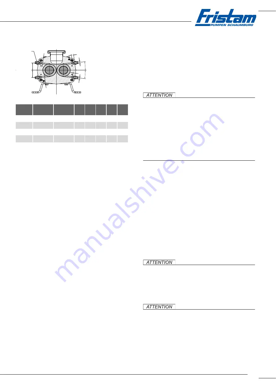
Inlet

A

Outlet

B

C

D

E

F

G

FDS 1

FDS 2

G¼" (m/f)

G¼" (m/f)

7.5°

42

12

Ø8

310

FDS 3

G¼" (m/f)

G¼" (m/f)

7.5°

50.5

12

Ø10 375.5

FDS 4

Table 2   

A-A

optional (4x)

B

A

C

C

D

D

E

E

F

F

Содержание FDS 1 Series

Страница 1: ...Original operating guide Assembly instructions Twin screw pump FDS series Pump type Pump no ...

Страница 2: ... laws protecting intellectual property Disseminating or altering the content of this operating guide is forbidden Moreover the content may not be copied disseminated altered or made available to third parties for commercial purposes The original version of this operating guide is the German version Other language versions are translations of the original German operating guide ...

Страница 3: ...mmissioning 10 6 List 11 6 1 Safety notices 11 6 2 Installation site 11 6 3 Reduction of noise and vibrations 11 6 4 Attach pump 11 6 5 Align coupling 11 6 6 Install pipelines 11 6 7 Establish electrical connection 12 6 8 Connect barrier or quench fluid optional 12 6 9 Cleaning 13 7 Operation 13 7 1 Safety notices 13 7 2 Commence operation 13 7 3 Observe operation 13 7 4 End operation 14 7 5 Remov...

Страница 4: ...t table 19 11 5 EC Declaration of Conformity 21 11 6 EC Declaration of Incorporation 21 12 Appendix 2 Assembly instructions optio nal for pump with bare shaft 22 12 1 Safety notice 22 12 2 Application 22 12 3 Nameplate 22 12 4 Transport without motor 22 12 5 Installation site 23 12 6 Mount pump 23 ...

Страница 5: ...ts The documentation consists of this operating guide Appendix 1 with tables on maintenance lubrication and tightening torques Appendix 2 with assembly instructions accompanying documents order documents data sheet supplier documentation motor coupling etc documentation on Fristam accessories if applicable certificates if applicable material certificates etc declaration of conformity or declaratio...

Страница 6: ...stroy the pump The presence of debris in the pumped medium may block and destroy the pump This operating guide describes standard Fristam pump aggrega tes In the event of exceptions and the installation of extras the operator is responsible for operation Conversions and modifications to the pump are only permitted after consulting with Fristam 2 4 Pump specific safety notices Unacceptable pressure...

Страница 7: ...accordance with applicab le regulations 2 7 3 Disposal of lubricating oil Oil and oily objects are to be disposed of in an environmen tally friendly manner in accordance with applicable regula tions 2 7 4 Disposal of pump 1 Dispose of hazardous and toxic residues in an environmen tally friendly manner and in accordance with applicable re gulations 2 Clean the pump carefully 3 Disassemble pump into...

Страница 8: ...3 Sizes 3 4 Add ons FDS twin screw pumps may be equipped with the following add ons among others Lining Stainless steel lining for the motor The lining is attached to the base frame Domed feet Domed feet on which to install the pump Domed feet are mounted on the base frame of the pump Additional add ons are possible Please contact Fristam if you have any questions 3 5 Type designation Fig 5 Type d...

Страница 9: ...edure 1 Pick up the pallet using the forklift 2 Slowly and smoothly transport the pallet to the destination and deposit there Fig 6 Transport by forklift 4 3 Transport by crane Falling parts Death by crushing serious bruising of limbs property damage Use only appropriate means of transport and lifting tackle For information on the weight of the pump see the pump nameplate and refer to Order docume...

Страница 10: ...st frost and heat preferably at 20 C to 25 C ventilated dust free All of the pump s moving parts must be turned every three months 5 2 Long term warehousing The following must be kept in mind if the pump is being stored for more than six months before placing the pump in storage completely disassemble the shaft seals and store separately In this regard please refer to Chapter 5 2 1 Storage of elas...

Страница 11: ...tor cooling 6 3 Reduction of noise and vibrations 6 3 1 Primary measures Operate the pump in the optimal working range Operate the pump without cavitation see Chapter 6 6 Install pipelines Page 11 Isolate suction and pressure line from vibrations Support the lines Align the lines Insert elements for vibration damping 6 3 2 Secondary measures Implement structural measures such as Sound insulation c...

Страница 12: ...ipelines flush with the pump connections using an angle 6 7 Establish electrical connection Electrostatic charge Electric shock Ground pipelines and the pump so that electrostatic charges can be dissipated The electrical connection may only be carried out by a qualified electrician Procedure 1 Observe the connection values on the motor nameplate The specified voltage must not be exceeded 2 Only co...

Страница 13: ...p both prior to and during operation 7 2 Commence operation Double shaft seal Loss of barrier fluid Damage to the shaft seal During operation make sure that Barrier fluid with sufficient pressure is flowing through the double shaft seal see information on the enclosed Data sheet The temperature of the barrier fluid is maintained at T 70 C 1 Open the valve in the suction line 2 Open the valve in th...

Страница 14: ...for the CIP Cleaning In Place method Observe the following indicative values during the CIP process Example cleaning process 1 Pre rinse with water 2 Caustic flushing with sodium hydroxide NaOH see Table 3 CIP cleaning Page 14 3 Perform an intermediate water rinse 4 Acid flushing with nitric acid HNO3 see Table 3 CIP clea ning Page 14 5 Final rinse with water The differential pressure of the pump ...

Страница 15: ...ed by Fristam may result in serious personal injury and property damage Please contact Fristam for any questions regarding approved spare parts Fristam maintains a record of all pumps delivered The following information is required when ordering spare parts 1 Serial number of the pump refer to the nameplate or the rim on the pump 2 For designations of spare parts and materials please refer to Orde...

Страница 16: ...d Page 16 2 Replace shaft seal see Chapter 10 9 2 Installation of the shaft seal Page 17 Pre mount the pump housing Install the shaft seal 3 Mount the pump housing 4 Mount the displacement device 5 Close the pump cover The exact procedure is described in the following chapters 10 8 Dismantle pump head 10 8 1 Dismantle pump housing and feed screws Preparation 1 Before dismantling refer to the enclo...

Страница 17: ...ot be mixed up under any circumstan ces They are assigned to the drive shaft or driven shaft and each have been marked with punches Note the markings before installing feed screws one frontal punch for the drive shaft two frontal punches for driven shaft 10 9 2 Installation of the shaft seal 1 Reinsert the shaft seal into the intermediate flange in accor dance with the sectional drawing anti torsi...

Страница 18: ...pe Maintenance activity Chapter Daily All Check the oil level See Chapter 10 4 Check the oil level Page 15 Daily Barrier and quench fluid option Check barrier or quench fluid See Chapter 10 3 Check the barrier and quench fluid optional Page 15 2000 h All in extreme operating conditions Oil change See Chapter 10 5 Change oil Page 15 4000 h All in normal conditions Oil change See Chapter 10 5 Change...

Страница 19: ...ction of rotation Carry out pipe and electrical connections properly Metallic noise Debris inside the pump Dismantle assess repair as needed Mechanical start up of the feed screws Feed screw nut is loose Dismantle rework Correct slackness setting tighten with tightening torque replace Excessive wear on bearings and gears wheels due to overloading or insufficient lubrication Dismantle assess repair...

Страница 20: ...or double shaft seal Barrier or rinse water pressure too low barrier water tubes are clogged shaft seal is encrusted or damaged Adjust barrier water inflow and outflow clean the barrier water tubes replace the shaft seal Barrier water contaminated or too hot Use drinking quality water at a maximum of 70 C 1 The geodetic head is the vertical distance between the surface of the suction side fluid le...

Страница 21: ...Gubener Str 1 31655 Stadthagen GERMANY hereby declares that the following product pump without mo tor Twin screw pump type FDS Serial number see cover page of the operating guide is an incomplete machine in accordance with Machinery Direc tive 2006 42 EC Annex II B The relevant fundamental safety and health protection require ments in accordance with Annex I of the aforementioned Direc tive have b...

Страница 22: ...Safety notices Falling or unsecured components Severe bruises Always wear safety shoes during all transport work Incorrect transport position of the pump Leakage of corrosive toxic or contaminating fluids Personal in jury and property damage caused by contamination Always transport pump in the installation position Open unsealed pipe connections Property damage caused by contaminants impacts or mo...

Страница 23: ...e round sling Death by crushing serious bruising property damage Do not let the round sling come into contact with sharp corners and edges Wrap the round sling around the housing and drive shaft see Fig 17 Transport with round sling Page 23 2 Double shaft seal Attention The round sling presses against the barrier water tubes Damage to double shaft seal Circumvent the barrier water tubes with the r...

Страница 24: ...the centre and angular offset of the drive shaft and gear shaft 5 Keep the deviations of the angular offset and shaft offset as low as possible Realign as necessary or shim components 6 Bolt the pump and gearbox onto the base frame or founda tion 7 Fasten the coupling in accordance with the coupling manu facturer s specifications 8 Establish a non contact guard coupling guard in accordan ce with M...

Страница 25: ...25 ...

Страница 26: ...FRISTAM Pumpen Schaumburg GmbH Kurt A Körber Chaussee 55 21033 Hamburg GERMANY Tel 49 0 5721 98206 0 E mail info fristam de FDS twin screw pumps DE 05 2016 R 0 0 ...

Отзывы: