


26
PB
OPERATION
Refrigeration Sequence Of Operation
A good understanding of the basic operation of the refrigeration system is essential for the service technician. Without this
understanding, accurate troubleshooting of refrigeration system problems will be more difficult and time consuming, if not (in
some cases) entirely impossible. The refrigeration system uses four basic principles in its operation which are as follows:
1
. “Heat always flows from a warmer body to a cooler body.”
2. “Heat must be added to or removed from a substance before a change in state can occur”
3. “Flow is always from a higher pressure area to a lower pressure area.”
4. “The temperature at which a liquid or gas changes state is dependent upon the pressure.”
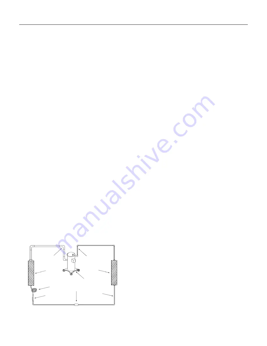
The refrigeration cycle begins at the compressor when a demand is received from the thermostat. Starting the compressor
creates a low pressure in the suction line which draws refrigerant gas (vapor) into the compressor. The compressor then
“compresses” this refrigerant vapor, raising its pressure and its (heat intensity) temperature.
The refrigerant leaves the compressor through the discharge line as a hot high pressure gas (vapor). The refrigerant enters the
condenser coil where it gives up some of its heat. The condenser fan moving air across the coil’s finned surface facilitates the
transfer of heat from the refrigerant to the relatively cooler outdoor air.
When a sufficient quantity of heat has been removed from the refrigerant gas (vapor), the refrigerant will “condense” (i.e.
change to a liquid). Once the refrigerant has been condensed (changed) to a liquid it is cooled even further by the air that
continues to flow across the condenser coil.
The design determines at exactly what point (in the condenser) the change of state (i.e. gas to a liquid) takes place. In all cases,
however, the refrigerant must be totally condensed (changed) to a liquid before leaving the condenser coil.
The refrigerant leaves the condenser coil through the liquid line as a warm high pressure liquid. It next will pass through the
refrigerant drier (if equipped). It is the function of the drier to trap any moisture present in the system, contaminants, and large
particulate matter.
The liquid refrigerant next enters the metering device. The metering device is called a capillary tube. The purpose of the
metering device is to “meter” (i.e. control or measure) the quantity of refrigerant entering the evaporator coil.
In the case of the capillary tube this is accomplished (by design) through size (and length) of device, and the pressure difference
present across the device. Since the evaporator coil is under a lower pressure (due to the suction created by the compressor)
than the liquid line, the liquid refrigerant leaves the metering device entering the evaporator coil. As it enters the evaporator
coil, the larger area and lower pressure allows the refrigerant to expand and lower its temperature (heat intensity). This
expansion is often referred to as “boiling” or atomizing. Since the unit’s blower is moving indoor air across the finned surface
of the evaporator coil, the expanding refrigerant absorbs some of that heat. This results in a lowering of the indoor air
temperature, or cooling.
The expansion and absorbing of heat cause the liquid refrigerant to evaporate (i.e. change to a gas). Once the refrigerant has
been evaporated (changed to a gas), it is heated even further by the air that continues to flow across the evaporator coil.
The particular system design determines at exactly what point (in the
evaporator) the change of state (i.e. liquid to a gas) takes place. In all
cases, however, the refrigerant must be totally evaporated (changed)
to a gas before leaving the evaporator coil.
The low pressure (suction) created by the compressor causes the
refrigerant to leave the evaporator through the suction line as a cool
low pressure vapor. The refrigerant then returns to the compressor,
where the cycle is repeated.
Suction
Line
Evaporator
Coil
Metering
Device
Refrigerant
Strainer
Discharge
Line
Condenser
Coil
Compressor
Refrigerant Drier Liquid
Line
Figure 301 (Sequence of Operation)
Содержание PDE07K Series
Страница 23: ...23 OPERATION DipSwitchFunction 3 4 4 Dip Switch Functions Settings Dip Switch 3 and 4 Disable No Function ...
Страница 39: ...39 UNIT DISASSEMBLY IndoorMotor Wheel HeatingElementAssembly FIGURE 401 Removal of Indoor Fan Wire Harness ...
Страница 41: ...41 UNIT DISASSEMBLY Indoor Motor Wheel Heating Element Assembly FIGURE 403 Removal of Indoor Fan Grommet ...
Страница 42: ...42 UNIT DISASSEMBLY Indoor Motor Wheel Heating Element Assembly Figure 404 Left side Bushing Bushing Housing ...
Страница 47: ...47 UNIT DISASSEMBLY Indoor Motor Wheel Heating Element Assembly Figure 409 Primary Secondary Limits ...
Страница 48: ...48 UNIT DISASSEMBLY OutdoorMotor Blade ShroudAssembly Figure 410 Remove Gussets and Fan Shroud ...
Страница 50: ...50 UNIT DISASSEMBLY ElectronicBoard ElectricalComponentReplacement Figure 412 Remove User Interface ...
Страница 51: ...51 UNIT DISASSEMBLY Electronic Board Electrical Component Replacement Figure 413 Remove User Interface ...
Страница 52: ...52 UNIT DISASSEMBLY Electronic Board Electrical Component Replacement FIGURE 414 Low Voltage Connections ...
Страница 53: ...53 UNIT DISASSEMBLY Electronic Board Electrical Component Replacement Figure 415 Power Cord and Housing ...
Страница 56: ...56 UNIT DISASSEMBLY Electronic Board Electrical Component Replacement Figure 418 Main Board Relay Board ...
Страница 58: ...58 UNIT DISASSEMBLY Electronic Board Electrical Component Replacement Figure 420 Transformer ...
Страница 59: ...59 UNIT DISASSEMBLY Electronic Board Electrical Component Replacement Figure 421 Transformer Removed ...
Страница 96: ...96 COMPONENTS TESTING TestingLineVoltage 208 230 265V AC FIGURE 709 LINE VOLTAGE ...


