background image

Errata for Revision 2.3

MCF5282 User’s Manual Errata, Rev. 15

Freescale Semiconductor

3

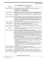
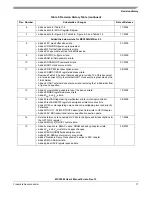
Table 10-14/Page 10-15

Change flag clearing mechanism for sources 24-26. They should read as follows:
Write ERR_INT = 1 after reading ERR_INT = 1
Write BOFF_INT = 1 after reading BOFF_INT = 1
Write WAKE_INT = 1 after reading WAKE_INT = 1

Table 12-7/Page 12-7

BAM bit field description, the first example should read “So, if CSAR0 = 0x0000 and 
CSMR0[BAM] = 0x0001” instead of “So, if CSAR0 = 0x0000 and CSMR0[BAM] = 0x0008”.

Table 10-2/Page 10-4

In footnote, remove mention of the SWIACK register, as it is not supported in the global 
IACK space.

Section 10.3.7/Page 10-16 Change last paragraph to: “In addition to the IACK registers within each interrupt controller, 

there are global LnIACK registers. A read from one of the global LnIACK registers returns 
the vector for the highest priority unmasked interrupt within a level for all interrupt 
controllers. There is no global SWIACK register. However, reading the SWIACK register 
from each interrupt controller returns the vector number of the highest priority unmasked 
request within that controller.”

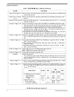
Table 15-1/Page 15-3

NOP command entry. Replace “SRAS asserted” with “SDRAM_CS[1:0] asserted”

Table 15-5/Page 15-7

Add the following note to the DACRn[CBM] field description:
Note:  It is important to set CBM according to the location of the command bit.

Section 16.5/Page 16-11

Remove last sentence in this section starting with “BCRn decrements...” since SAA bit is 
not supported.

Chapter 17

The maximum buffer size of the FEC is 2032 bytes. Replace any mention of the max size 

being 2047 bytes with 2032 bytes.

Section 17.4.6/Page 17-7

Add the following subsection entitled “Duplicate Frame Transmission”:
The FEC fetches transmit buffer descriptors (TxBDs) and the corresponding transmit data 
continuously until the transmit FIFO is full. It does not determine whether the TxBD to be 
fetched is already being processed internally (as a result of a wrap). As the FEC nears the 
end of the transmission of one frame, it begins to DMA the data for the next frame. In order 
to remain one BD ahead of the DMA, it also fetches the TxBD for the next frame. It is 
possible that the FEC will fetch from memory a BD that has already been processed but not 
yet written back (that is, it is read a second time with the R bit still set). In this case, the data 
is fetched and transmitted again.
Using at least three TxBDs fixes this problem for large frames, but not for small frames. To 
ensure correct operation for either large or small frames, one of the following must be true:
 • The FEC software driver ensures that there is always at least one TxBD with the ready 

bit cleared.

 • Every frame uses more than one TxBD and every TxBD but the last is written back 

immediately after the data is fetched.

 • The FEC software driver ensures a minimum frame size, 

n

. The minimum number of 

TxBDs is then (Tx FIFO Size

÷

(+ 4)) rounded up to the nearest integer (though the 

result cannot be less than three). The default Tx FIFO size is 192 bytes; this size is 
programmable.

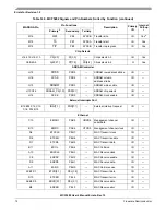
Table 17-9/Page 17-17

Correct MIB block counters end addresses to 0x12FF.

Table 17-11/Page 17-19

Add RMON_R_DROP with an IPSBAR Offset of 0x1280 and a description of ‘Count of 

frames not counted correctly’.

Figure 17-26/Page 17-41

Change EMRBR register address from “ 0x11B8” to “ 0x1188”.

Section 20.5.13/Page 20-12 Deleted reference to nonexistent CF bits in the figure and bit descriptions for the GPTFLG2 

register.

Table 1. MCF5282UM Rev 2.3 Errata (continued)

Location

Description

Содержание MCF5282

Страница 1: ...MCF5282 ColdFire Microcontroller User s Manual order number MCF5282UM For convenience the addenda items are grouped by revision Please check our website at http www freescale com for the latest update...

Страница 2: ...e to NOTE Peripheral IPSBAR space should not be cached The combination of the CACR defaults and the two ACRn registers must define the non cacheable attribute for this address space Figure 5 1 Page 5...

Страница 3: ...on entitled Duplicate Frame Transmission The FEC fetches transmit buffer descriptors TxBDs and the corresponding transmit data continuously until the transmit FIFO is full It does not determine whethe...

Страница 4: ...by writing a one instead of a zero Table 26 1 Page 26 5 Change description field for DTOUT1 from DMA timer 1 output Port TD 3 to DMA timer 1 output Port TD 2 Change description field for DTIN0 from DM...

Страница 5: ...hanged to Invalidate 2 KByte instruction cache Figure 6 3 6 6 Changed bit 8 to write only instead of read write Table 6 10 6 15 Removed selected by BKSL 1 0 as these are internal signal names not nece...

Страница 6: ...it as a zero to To clear an interrupt flag first read the flag as a one then write it as a one Chapter 33 It is crucial during power up that VDD never exceeds VDDH by more that 0 3V There are diode d...

Страница 7: ...5 2 Replace the description of PRI1 and PRI2 with the following Table 5 1 5 3 Add the following note to the SPV bit description The BDE bit in the second RAMBAR register must also be set to allow dual...

Страница 8: ...allow a level 7 IRQ to generate a wakeup That is the wakeup mask value used by the interrupt controller must be in the range of 0 6 Figure 12 4 12 8 Change CSCRn to reflect that AA is set to 1 at res...

Страница 9: ...he port C and D pins and PJ 5 4 BS 1 0 can be configured as general purpose input output I O 32 2 32 7 Added additional device number order information to Table 32 2 Chapter 33 Delete references to TA...

Страница 10: ...ow Table 14 3 MCF5282 Signals and Pin Numbers Sorted by Function MAPBGA Pin Pin Functions Description Primary I O Internal Pull up 1 Primary2 Secondary Tertiary Reset R11 RSTI Reset in I Yes P11 RSTO...

Страница 11: ...B4 A4 B3 A3 A 20 16 PF 4 0 Address bus O Yes A2 B1 B2 C1 C2 C3 D1 D2 A 15 8 PG 7 0 Address bus O Yes D3 D4 E1 E2 E3 E4 F1 F2 A 7 0 PH 7 0 Address bus O Yes F3 G1 G2 G3 G4 H1 H2 H3 D 31 24 PA 7 0 Data...

Страница 12: ...4 C15 C16 D14 D15 IRQ 7 1 PNQ 7 1 External interrupt request I O Ethernet C10 EMDIO PAS5 URXD2 Management channel serial data I O B10 EMDC PAS4 UTXD2 Management channel clock I O A8 ETXCLK PEH7 MAC Tr...

Страница 13: ...U0 receive data I O T7 UTXD0 PUA0 U0 transmit data I O C10 EMDIO PAS5 URXD2 U2 receive data I O B10 EMDC PAS4 UTXD2 U2 transmit data I O D16 CANRX PAS3 URXD2 U2 receive data I O E13 CANTX PAS2 UTXD2 U...

Страница 14: ...IP PE0 SYNCB Timer B synchronization input I O Yes DMA Timers K16 DTIN3 PTC3 URTS1 URTS0 Timer 3 in I O K15 DTOUT3 PTC2 URTS1 URTS0 Timer 3 out I O K14 DTIN2 PTC1 UCTS1 UCTS0 Timer 2 in I O K13 DTOUT2...

Страница 15: ...I TDI Debug data in TAP data in I Yes7 T10 DSO TDO Debug data out TAP data out O C12 D12 A13 B13 DDATA 3 0 PDD 7 4 Debug data I O C13 A14 B14 A15 PST 3 0 PDD 3 0 Processor status data I O Test N10 TES...

Страница 16: ...umber Substantive Changes Date of Release 0 Initial release 07 2003 1 Added page erase verify errata for Chapter 6 ColdFire Flash Module CFM 09 2003 2 Added errata for UART interrupt status register A...

Страница 17: ...he 16 bit divider from a figure and equation 08 2005 12 Added core watchdog unable to reset the device errata Added EMRBR register address errata Added IOH and IOL errata 12 2005 13 Added FlexCAN flag...

Страница 18: ...particular purpose nor does Freescale Semiconductor assume any liability arising out of the application or use of any product or circuit and specifically disclaims any and all liability including with...

Отзывы: