


DF4000 Rev0204
3
List of Tables
Table 1. Program Code Quick Reference ................................................................ 23
List of Illustrations
Figure 1. Controls and Indicators .............................................................................. 7
Figure 2. Display Module Mounting Dimensions .................................................... 9
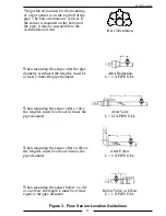
Figure 3. Flow Sensor Location Guidelines............................................................ 11
Figure 4. Saddle Clamp Installation ........................................................................ 13
Figure 5. Weldment Installation .............................................................................. 15
Figure 6. Typical Datalink ....................................................................................... 17
Figure 7. Typical Programming Displays ................................................................ 20
Figure 8. Primary Display Wiring ........................................................................... 28
Figure 9. Remote Display Wiring............................................................................ 29
Figure 10. Parts List ................................................................................................. 30


