


DF4000 Rev0204
12
Saddle Clamp Installation
Note:
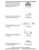
Ensure that the mounting location meets the requirements for uniform
water flow. (Refer to Flow Sensor Location.)
Note:
Ensure that there is enough room for the saddle clamp, sensor, and
connector to fit. (Refer to Figure 4.)
1. Drill and deburr a 1-11/16" to 1-3/4" diameter hole at mounting location.
2. Clean pipe surface in area where saddle clamp gasket will seal.
Note:
The sensor housing is epoxied in the saddle clamp with the alignment
tab in the correct position and is not meant to be removed.
3. Place saddle clamp over hole with sensor housing centered.
4. Tighten saddle clamp nuts until the gasket makes a good tight seal.
5. Insert flow sensor into sensor housing. Align flat spot on sensor rim with
alignment tab and make sure o-ring is in groove.
Note:
The retainer cap only needs to be hand tightened. There is an inside
lip that will stop the cap from turning when it makes contact with the
alignment tab. This provides the correct pressure to make the seal at the
o-ring. Make sure the flow sensor does not disengage from the alignment
tab and rotate.
6. Install retainer cap and hand tighten.
7. Connect cable from display module to flow sensor. (Refer to Wiring section.)


