background image

18

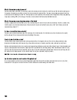
What is the maximum output pressure?

The Inline will maintain a “NO-FLOW” system pressure equal to the incoming pressure (psi) plus the shut-off pressure from the pump operating curve. 
For example, if the input pressure is 38 psi, at shut off the system will boost an additional 55 psi. This means ALL plumbing downstream of the Inline 
would be subject to maintaining 93 psi (38 + 55). If this high pressure is undesirable due to the condition and/or configuration of the existing plumbing 
or appliances, installing a PRV on the discharge of the Inline is recommended to limit the maximum distributed pressure.

What is the maximum operating temperature of the Inline?

The Inline is equipped with two temperature sensors. One is installed integral to the motor to protect the motor windings. The other is installed in the 
control head and senses the internal temperature of the water. In both cases, the unit will fault at a max temp of 120 °F and turn back on when the 
temperature drops below 95 °F.

Do I have to install the Inline vertically?

The Inline can be installed horizontally as long as the discharge port is directed upwards. This orientation places the air bleed valve in the upward 
position, allowing it to function properly during the initial priming of the pump.

How do I prime the Inline system?

The Inline will need to be properly primed before initial operation (before unit is plugged in). Because there are two spring-loaded check valves 
integrated into the Inline head, a small amount (1.5 psi) of positive water pressure is needed to open these valves and properly prime the unit.

With the unit fully plumbed into the system, open the water supply valve and allow pressurized water to flow through the unit. You will probably want 
to place a small bucket under the Inline tank to capture water that is expelled from the unit during priming. With a small flathead screwdriver, slowly 
open the air bleed valve (located directly under the outlet) to allow air to exit the internal pump and tank. When the valve stops sputtering and only a 
fine stream of water is being expelled, close the air bleed valve. The unit is now primed and ready for operation.

NOTE: 

Do not open the air bleed valve when the pump is running.

Can the Inline system be used in suction-lift applications?

It is not recommended to use the Inline in suction lift applications greater than five feet lift. A secondary pressurized water source (i.e. hose from 
municipality or 3' riser pipe) may be required in order to provide adequate pressurized priming as described above.

Содержание Inline400

Страница 1: ...INLINE PRESSURE BOOSTING SYSTEM Owner s Manual ...

Страница 2: ...ent should be installed by technically qualified personnel Failure to install it in compliance with national and local electrical and plumbing codes and within Franklin Electric recommendations may result in electrical shock or fire hazard unsatisfactory performance or equipment failure Installation information is available through pump manufacturers and distributors or directly from Franklin Elec...

Страница 3: ...lay 6 Installation 7 Location Orientation 7 Typical Residential Installation 8 Installation Procedure 9 Priming 10 Operation 11 Maintenance 13 Troubleshooting Guide 16 Frequently Asked Questions 17 Appendix 1 Inline 400 Pressure Boosting System Performance Curve 19 Appendix 2 Friction Loss Tables 20 Limited Warranty 24 ...

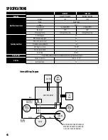
Страница 4: ...essure psi 55 MAX system pressure psi 95 Sound Pressure Level dB A 55 Plumbing Connections 1 1 4 NPT Max Suction Lift feet 5 Drain Plug 1 4 NPT Enclosure Type Acceptable for indoor outdoor use with protective cover CSA Enclosure Type 3 Unit Size External Dimensions 29 6 x 9 2 x 8 9 Net Weight lbs 35 HALL PCB MOTOR MAIN PCB ASSEMBLY CAPACITOR BLACK WIRE FROM MAIN PCB AND BLACK WIRE FROM MOTOR MUST ...

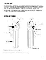
Страница 5: ...ther vertically or horizontally while also enabling the system to work with virtually any existing plumbing configuration The Franklin Electric Inline System provides consistent pressure boosting using advanced electronics to drive and control a standard Franklin Electric pump and motor according to the pressure boosting demands of the application SYSTEMCOMPONENTS Mounting Bolts 2 1 4 NPT Drain Pl...

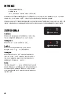
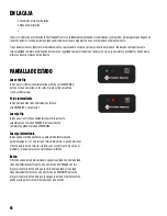
Страница 6: ...wered and is turned ON but not currently running The green solid light will only be present when no faults are active Flashing Green Indicates the pump is powered turned ON and running Solid Red Indicates the control is powered but currently in the OFF mode Pressing the button will toggle the unit into the ON mode Flashing Red Indicates a FAULT has occurred The unit will automatically attempt to r...

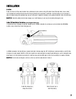
Страница 7: ...y It is preferred for ease of priming to install the Inline 400 unit in a VERTICAL orientation The unit however can be installed in the HORIZONTAL position as long as the air bleed valve is facing upwards Rotate the entire pump to change flow direction Rotate the control cap to orient status display Air bleed Valve In VERTICAL installations the Inline 400 comes standard with the flow direction bei...

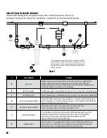
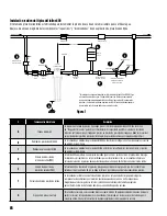
Страница 8: ...r than 2 psi below pressure setting of the outlet pressure switch must never exceed 80 psi B INLET Pressure Gauge An INLET pressure gauge is recommended for the purpose of system set up operation and troubleshooting C OUTLET Pressure Gauge An OUTLET pressure gauge is recommended for the purpose of system set up operation and troubleshooting D Outlet pressure reducing Valve PRV This Inline 400 will...

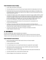
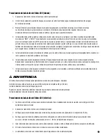
Страница 9: ...located within 5 of the discharge of the pump There should be no control check valve between the pressure tank and the Inline Pressure Boosting System The tank pre charge pressure shall be no greater than 2 psi below the outlet pressure switch setting never exceed 80 psi 7 Install a pressure relief valve downstream of the Inline 400 The discharge must be plumbed to a drain rated for maximum pump o...

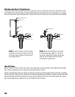
Страница 10: ...e unit Place a small bucket under the Inline tank to capture water that is expelled from the air bleed during priming With a small flathead screwdriver slowly open the air bleed valve located directly under the outlet to allow air to exit the internal pump and tank When the valve stops sputtering and only a fine stream of water is being expelled close the air bleed valve The unit is now primed and...

Страница 11: ...rate until the water is running clear No further priming should be needed unless the pump is drained or there is a leak in the suction plumbing NOTE NEVER OPEN THE BLEED WITH THE PUMP ON as this may allow air to ENTER the pump rather than expel it from the system Effect of System Leaks Leaking water systems may cause the Inline Pressure Boosting System to cycle more than expected This is due to th...

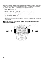
Страница 12: ...s and remove the cap NOTE Be careful when removing the control cap as there is an electrical cable attached to the head 3 Using a 7 32 hex wrench turn the internal discharge pressure switch screw clockwise one full turn This should raise the switch cutoff by 10 12 psi 4 Replace the control cap and re install 6 screws 5 If desired not required adjust the pressure tank pre charge pressure to a maxim...

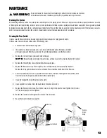
Страница 13: ... be under pressure As such close both the inlet and outlet valves and drain all pressurized water from the system prior to performing maintenance on the flow switch 3 Remove the 6 control cap screws and remove the cap NOTE Be careful when removing the control cap as there is an electrical cable attached to the head 4 Remove the three Phillips screws that hold the flow cap in place 5 Remove the flo...

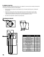
Страница 14: ...n and red LEDs blink indicating calibration is complete Release the button and the red LED should come on solid indicating calibration was successful 3 Open valves taps to begin water flow and confirm unit is operating properly Outline Dimensions for Inline 400 Model Description Order No Pump Housing Wrench 305572001 Inlet or Outlet Pressure Switch 40 psi 305572007 Replacement Pump Housing 3055720...

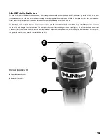
Страница 15: ...f the Inline 400 unit The installation of the enclosed protective weather cover is simple After the Inline 400 unit has been installed simply attach the protective cover over the top of the unit using the reclosable fastener The clear protective cover allows viewing of the operation lights of the unit but does not allow access to the user interface button In order to press the user interface butto...

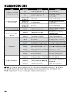
Страница 16: ...between tank and unit Place check valve after pressure tank Unit won t turn on Solid RED Unit is turned OFF Press the power button on the user interface Flashing RED Overvoltage input voltage higher than 10 Check the supply voltage and correct if possible Flashing RED Undervoltage input voltage lower than 10 Check the supply voltage and correct if possible Flashing RED Overheating due to excessive...

Страница 17: ...loped Overheat greater than 120 F internal water temperature These are also Inline 400 faults which are indicated by a red blinking light on the control cap What is the purpose of the pressure tank The pressure tank serves two purposes 1 It allows for small volumes of water to be used without starting the Inline 2 It adds a pressure buffer to the system in order to absorb undesired pressure spikes...

Страница 18: ...ve in the upward position allowing it to function properly during the initial priming of the pump How do I prime the Inline system The Inline will need to be properly primed before initial operation before unit is plugged in Because there are two spring loaded check valves integrated into the Inline head a small amount 1 5 psi of positive water pressure is needed to open these valves and properly ...

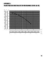
Страница 19: ...19 APPENDIX1 INLINEPRESSUREBOOSTINGSYSTEMPERFORMANCECURVE 60HZ 60 140 120 100 80 60 40 20 0 0 0 10 20 30 40 50 60 70 80 90 0 1 2 3 4 5 5 10 20 25 15 50 40 40 30 20 10 0 30 20 10 0 m psi gpm lpm m3 h ft ...

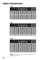
Страница 20: ... 0 64 1 53 1 13 8 1 72 2 04 1 10 2 04 1 92 10 2 15 3 09 1 66 2 55 2 90 12 2 57 4 33 2 32 3 06 4 07 14 3 00 5 76 3 09 3 57 5 41 16 3 43 7 38 3 96 4 08 6 93 18 3 86 9 18 4 92 4 59 8 62 20 4 29 11 16 5 98 5 11 10 48 25 5 36 16 87 9 05 6 38 15 85 Flow gpm Velocity ft s Friction Loss ft hd 100 Velocity ft s Fric Loss ft hd 100 Steel C 100 PVC C 140 Copper C 130 2 0 74 0 60 0 32 0 78 0 41 4 1 48 2 15 1 ...

Страница 21: ...21 NOTES ...

Страница 22: ...22 NOTES ...

Страница 23: ...23 NOTES ...

Страница 24: ...CHASER OR ANY THIRD PARTY FOR ANY AND ALL i INCIDENTAL EXPENSES OR OTHER CHARGES COSTS EXPENSES INCLUDING COSTS OF INSPECTION TESTING STORAGE OR TRANSPORTATION OR ii DAMAGES INCLUDING CONSEQUENTIAL SPECIAL DAMAGES PUNITIVE OR INDIRECT DAMAGES INCLUDING WITHOUT LIMITATION LOST PROFITS LOST TIME AND LOST BUSINESS OPPORTUNITIES REGARDLESS OF WHETHER FRANKLIN IS OR IS SHOWN TO BE AT FAULT AND REGARDLE...

Страница 25: ...SISTEMA DE PRESURIZACIÓN INLINE Manual del usuario ...

Страница 26: ...bajar en el producto o cerca de este Este equipo debe ser instalado por personal técnicamente calificado Si la bomba se instala en contravención de las regulaciones locales y nacionales de electricidad y plomería y las recomendaciones de Franklin Electric podrían producirse descargas eléctricas riesgos de incendio un rendimiento insatisfactorio o fallas del equipo Puede pedir información sobre la ...

Страница 27: ...ón 7 Ubicación Orientación 7 Instalación residencial típica 8 Procedimiento de instalación 9 Cebado 10 Funcionamiento 11 Mantenimiento 13 Guía de solución de problemas 16 Preguntas frecuentes 17 Apéndice 1 Curva de desempeño del sistema de presurización Inline 400 19 Apéndice 2 Tablas de pérdida por fricción 20 Garantía limitada 24 ...

Страница 28: ...sión sonora dB A 55 Conexiones de tubería 1 1 4 NPT Elevación de succión máxima pies 5 Tapón de drenado 1 4 NPT Tipo de gabinete Aceptable para uso en el interior exterior con cubierta de protección Gabinete CSA 3 Tamaño de la unidad Dimensiones externas 29 6 x 9 2 x 8 9 Peso neto lb 35 Diagrama de cableado interno PCB de HALL MOTOR CONJUNTO DE LA PCB PRINCIPAL CONDENSADOR EL CABLE NEGRO DE LA PCB...

Страница 29: ...también deja funcionar al sistema con virtualmente cualquier configuración de tubería existente El sistema Inline de Franklin Electric proporciona una presurización constante usando una electrónica avanzada para accionar y controlar una bomba y un motor estándar de Franklin Electric de acuerdo a las demandas de aumento de presión de la aplicación COMPONENTESDELSISTEMA Pernos de montaje 2 Tapón de ...

Страница 30: ...ará encendida si no hay fallas activas Verde intermitente Indica que la bomba tiene alimentación eléctrica está ENCENDIDA y en operación Luz roja fija Indica que el control tiene alimentación eléctrica pero está actualmente en el modo APAGADO Presionar el botón cambiará la unidad al modo de ENCENDIDO Luz roja intermitente Indica que ha ocurrido una FALLA La unidad intentará reiniciarse automáticam...

Страница 31: ...tar la ceba instalar la unidad Inline 400 en una orientación VERTICAL La unidad sin embargo se puede instalar en la posición HORIZONTAL siempre que la válvula de salida de aire esté apuntando hacia arriba Rote la bomba completa para cambiar la dirección del flujo Rote la tapa de control para orientar la pantalla de estado En las instalaciones VERTICALES el Inline 400 viene de manera estándar con l...

Страница 32: ...resión del interruptor de presión de salida y nunca debe exceder 80 psi B Medidor de presión de ENTRADA Se recomienda un medidor de presión de ENTRADA a efectos de la configuración funcionamiento y solución de problemas del sistema C Medidor de presión de SALIDA Se recomienda un medidor de presión de SALIDA a efectos de la configuración funcionamiento y solución de problemas del sistema D Válvula ...

Страница 33: ...ngo de 5 pies de la descarga de la bomba No debe haber una válvula de control retención entre el tanque de presión y el sistema de presurización Inline La presión de precarga de la cisterna no debe ser mayor de 2 psi por debajo del ajuste del interruptor de presión de salida y nunca exceder 80 psi 7 Instale una válvula de alivio después de Inline 400 La descarga debe estar conectada a un drenaje c...

Страница 34: ...line para capturar el agua que se expulsa de la salida de aire al cebar Con un destornillador de cabeza plana pequeño abra lentamente la válvula de salida de aire localizada directamente debajo de la salida para permitir que salga el aire de la bomba interna y el tanque Cuando la válvula deje de barbotear y expulse solamente un chorro fino de agua cierre la válvula de salida de aire La unidad ahor...

Страница 35: ...que el agua esté corriendo limpia No se necesitará cebar nuevamente a menos que se drene la bomba o haya una fuga en la tubería de succión NOTA NUNCA ABRA LA SALIDA CON LA BOMBA FUNCIONANDO ya que esto puede permitir que ENTRE aire a la bomba en vez de sacarlo del sistema Efecto de las fugas del sistema Los sistemas con fugas pueden ocasionar que el Sistema de presurización Inline tenga un ciclo d...

Страница 36: ...r la tapa de control ya que hay un cable eléctrico conectado a la cabeza 3 Usando una llave hexagonal de 7 32 gire el tornillo del interruptor de presión de descarga interna una vuelta completa en sentido de las manecillas del reloj Esto debe elevar el corte del interruptor de 10 a 12 psi 4 Coloque de nuevo la tapa de control y vuelva a instalar los 6 tornillos 5 Si es necesario no es necesario aj...

Страница 37: ... tanto la válvula de entrada como la de salida y drene toda el agua presurizada del sistema antes de dar mantenimiento en el interruptor de flujo 3 Extraiga los 6 tornillos de la tapa de control y quite la tapa NOTA Tenga cuidado al quitar la tapa de control ya que hay un cable eléctrico conectado a la cabeza 4 Extraiga los tres tornillos Phillips que mantienen la tapa de flujo en su lugar 5 Quite...

Страница 38: ...alizó la calibración Libere el botón y el indicador LED rojo debe quedar iluminado fijo indicando que la calibración fue exitosa 3 Abra las válvulas grifos para comenzar el flujo del agua y confirmar que la unidad está funcionando apropiadamente Esquema de dimensiones del Inline 400 Descripción del modelo No de pedido Llave para la carcasa de la bomba 305572001 Interruptor de presión 40 psi de ent...

Страница 39: ...Inline 400 La instalación de la cubierta de protección contra el clima del gabinete es simple Luego de que la unidad Inline 400 haya sido instalada simplemente fije la cubierta de protección por encima de la unidad con sujetador recerrable La cubierta de protección transparente permite ver el funcionamiento de las luces de la unidad pero no permite el acceso al botón de la interfaz del usuario Par...

Страница 40: ...e el tanque y la unidad Coloque la válvula de retención después del tanque de presión La unidad no enciende Luz ROJA fija La unidad está APAGADA Presione el botón de encendido en la interfase del usuario Luz ROJA intermitente Sobrevoltaje voltaje de entrada mayor de 10 Revise el suministro de voltaje y corríjalo si es posible Luz ROJA intermitente Bajo voltaje voltaje de entrada menor de 10 Revise...

Страница 41: ...ntamiento temperatura interna del agua mayor que 120 F Estas son fallas del Inline 400 que también se indican por una luz roja intermitente en la tapa de control Cuál es el propósito del tanque de presión El tanque de presión sirve para dos propósitos 1 Permite que se usen volúmenes pequeños de agua sin arrancar el Inline 2 Agrega un amortiguador de presión al sistema para poder absorber los picos...

Страница 42: ... apropiadamente durante el cebado inicial de la bomba Cómo cebo el sistema Inline El Inline necesitará cebarse apropiadamente antes de la operación inicial antes de que se conecte Como hay dos válvulas de retención de resorte integradas a la cabeza del Inline se necesita una cantidad pequeña de presión positiva 1 5 psi de agua para abrir estas válvulas y cebar apropiadamente la unidad Con la unida...

Страница 43: ... APÉNDICE1 CURVADEDESEMPEÑODELSISTEMADEPRESURIZACIÓNINLINE 60HZ 60 140 120 100 80 60 40 20 0 0 0 10 20 30 40 50 60 70 80 90 0 1 2 3 4 5 5 10 20 25 15 50 40 40 30 20 10 0 30 20 10 0 m psi gpm lpm pies m3 h ...

Страница 44: ... 29 1 20 0 64 1 53 1 13 8 1 72 2 04 1 10 2 04 1 92 10 2 15 3 09 1 66 2 55 2 90 12 2 57 4 33 2 32 3 06 4 07 14 3 00 5 76 3 09 3 57 5 41 16 3 43 7 38 3 96 4 08 6 93 18 3 86 9 18 4 92 4 59 8 62 20 4 29 11 16 5 98 5 11 10 48 25 5 36 16 87 9 05 6 38 15 85 Flujo gpm Velocidad pies s Pérdida por fricción pies de carga hidráulica 100 pies Velocidad pies s Pérdida por fricción pies de carga hidráulica 100 ...

Страница 45: ...21 NOTAS ...

Страница 46: ...22 NOTAS ...

Страница 47: ...23 NOTAS ...

Страница 48: ...CONSECUENCIALES DAÑOS ESPECIALES DAÑOS PUNITIVOS O INDIRECTOS INCLUYENDO EN CARÁCTER ENUNCIATIVO Y NO LIMITATIVO PÉRDIDA DE GANANCIAS PÉRDIDA DE TIEMPO Y PÉRDIDA DE OPORTUNIDADES COMERCIALES SIN IMPORTAR SI FRANKLIN ES O SE DEMUESTRA QUE TIENE LA CULPA Y SIN IMPORTAR SI EXISTE O SE HA MOSTRADO QUE HA HABIDO UN DEFECTO EN LOS MATERIALES O MANO DE OBRA NEGLIGENCIA EN LA FABRICACIÓN O DISEÑO O UNA OM...

Страница 49: ...SYSTÈME DE SURPRESSION INLINE Manual du propriétaire ...

Страница 50: ...nstallé par une personne qualifiée sur le plan technique Une installation qui ne respecte pas les codes nationaux et locaux de l électricité et de la plomberie et les recommandations de Franklin Electric est susceptible de provoquer une décharge électrique un incendie un rendement insatisfaisant ou une défaillance de l équipement De l information sur l installation est disponible auprès des fabric...

Страница 51: ...état 6 Installation 7 Emplacement Orientation 7 Installation résidentielle typique 8 Procédure d installation 9 Amorçage 10 Utilisation 11 Entretien 13 Guide de dépannage 16 Foire aux questions 17 Annexe 1 Courbe de rendement du système de surpression Inline 400 19 Annexe 2 Tableaux de perte de charg 20 Garantie limitée 24 ...

Страница 52: ... Niveau sonore dbA 55 Connexions de plomberie MNPT 1 1 4 po 31 75 mm Hauteur d aspiration max pi 5 Bouchon de vidange NPT 1 4 po 6 35 mm Type de boîtier Acceptable pour l utilisation à l intérieur ou à l extérieur avec un couvercle protecteur Boîtier CSA 3 Dimensions de l unité Dimensions extérieures 29 6 po x 8 5 po x 9 2 po 75 2 cm x 23 4 cm x 22 6 cm Poids net lb 35 PCB HALL MOTEUR ASSEMBLAGE P...

Страница 53: ...système de fonctionner avec presque n importe quelle configuration de plomberie existante Le système Inline de Franklin Electric fournit une surpression constante au moyen de composants électroniques avancés afin d entraîner et de contrôler une pompe et un moteur standards Franklin Electric en fonction des demandes de surpression de l application COMPOSANTSDUSYSTÈME 2 boulons de fixation Bouchon d...

Страница 54: ...ixe ne s allume que lorsqu aucune défaillance n est active Vert clignotant Indique que la pompe est sous tension allumée et en marche Rouge fixe Indique que le contrôle est sous tension mais est en mode arrêt Appuyez sur le bouton pour faire passer l unité en mode marche Rouge clignotant Indique qu une DÉFAILLANCE est survenue L appareil tentera automatiquement de redémarrer Si vous devez redémarr...

Страница 55: ...l unité Inline 400 dans l orientation VERTICALE L unité cependant peut être installée en position HORIZONTALE tant que la soupape d évacuation d air est orientée vers le haut Faites pivoter la pompe au complet pour changer la direction du débit Faites pivoter le capuchon de contrôle pour orienter l affichage d état Dans les installations VERTICALES l unité Inline 400 est livrée de série avec une d...

Страница 56: ... de précharge du réservoir ne doit pas dépasser 2 psi en dessous du réglage de pression du pressostat de sortie et ne doit jamais dépasser 80 psi B Manomètre d ENTRÉE Un manomètre d ENTRÉE est recommandé à des fins de configuration d utilisation et de dépannage du système C Manomètre de SORTIE Un manomètre de SORTIE est recommandé à des fins de configuration d utilisation et de dépannage du systèm...

Страница 57: ... du refoulement de la pompe Il ne doit pas y avoir de clapet anti retour ou de soupape de contrôle entre le réservoir pressurisé et le système de surpression Inline La pression de précharge du réservoir ne doit pas dépasser 2 psi en dessous du réglage de la pression de sortie et ne dépasse jamais 80 psi 7 Installez une soupape de sûreté en aval du Inline 400 Le refoulement doit être raccordé à un ...

Страница 58: ... l eau qui est évacuée par l évacuation d air pendant l amorçage Au moyen d un petit tournevis à tête plate ouvrez lentement la soupape d évacuation d air située directement sous la sortie afin de permettre à l air de sortir du réservoir et de la pompe interne Lorsque la soupape cesse de crachoter et que seul un mince filet d eau en sort fermez la soupape d évacuation d air L unité est alors amorc...

Страница 59: ... ne devrait être nécessaire sauf en cas de vidange de la pompe ou de fuite dans la plomberie d aspiration REMARQUE N OUVREZ JAMAIS LA SOUPAPE D ÉVACUATION ALORS QUE LA POMPE FONCTIONNE car cela peut permettre à de l air d ENTRER dans la pompe plutôt que de sortir du système Effets de fuites du système Des systèmes d eau avec fuites peuvent faire fonctionner le système de surpression Inline plus qu...

Страница 60: ... Faites preuve de prudence en enlevant le capuchon de contrôle car un câble électrique est fixé à la tête 3 Au moyen d une clé hexagonale de 7 32 po 5 56 mm tournez la vis de l interrupteur de pression de refoulement interne d un tour complet dans le sens horaire Cela devrait accroître la pression de coupure de l interrupteur de 10 12 psi 4 Replacez le capuchon de contrôle et réinstallez les 6 vis...

Страница 61: ...z toute l eau sous pression du système avant de commencer les travaux d entretien de l interrupteur de débit 3 Retirez les 6 vis du capuchon de contrôle puis enlevez ce dernier REMARQUE Faites preuve de prudence en enlevant le capuchon de contrôle car un câble électrique est fixé à la tête 4 Retirez les trois vis Phillips qui maintiennent le capuchon de débit en place 5 Retirez le capuchon de cont...

Страница 62: ...alibration est terminée Relâchez le bouton et les voyants devraient s allumer en continu indiquant ainsi la réussite de la calibration 3 Ouvrez les soupapes robinets pour démarrer le débit et confirmez que l unité fonctionne correctement Dimensions hors tout de l unité Inline 400 Description du modèle No de commande Clé de boîtier de pompe 305572001 Interrupteur de pression d entrée ou de sortie 4...

Страница 63: ... unité Inline 400 L installation du couvercle ci inclus de protection contre les intempéries est simple Une fois que l unité Inline 400 a été installée fixez simplement le couvercle protecteur sur le dessus de l unité au moyen fixation refermable Le couvercle de protection transparent permet d examiner les voyants de fonctionnement de l unité mais ne donne pas accès au bouton d interface utilisate...

Страница 64: ...é Placez le clapet anti retour après le réservoir pressurisé L unité ne démarre pas ROUGE fixe L unité est fermée Appuyez sur le bouton d alimentation sur l interface utilisateur ROUGE clignotant Surtension le voltage d entrée est supérieur à 10 Vérifiez le voltage d alimentation et corrigez le si possible ROUGE clignotant Sous tension le voltage d entrée est inférieur à 10 Vérifiez le voltage d a...

Страница 65: ...éée Surchauffe température de l eau interne supérieure à 120 F 49 C Il s agit aussi de défaillances de l unité Inline 400 indiquées par un voyant clignotant rouge sur le capuchon de contrôle Quel est le rôle du réservoir pressurisé Le réservoir pressurisé remplit deux rôles 1 Il permet l utilisation de petits volumes d eau sans démarrage de l unité Inline 2 Il ajoute un tampon de pression au systè...

Страница 66: ...ir vers le haut ce qui lui permet de fonctionner correctement pendant l amorçage initial de la pompe Comment amorce t on le système Inline L unité Inline doit être amorcée de manière appropriée avant son fonctionnement initial avant que l unité ne soit branchée Puisque deux clapets anti retour à ressort sont intégrés à la tête Inline une petite pression d eau positive 1 5 psi est requise pour ouvr...

Страница 67: ...RBEDERENDEMENTDUSYSTÈMEDESURPRESSIONINLINE 60HZ 60 140 120 100 80 60 40 20 0 0 0 10 20 30 40 50 60 70 80 90 0 1 2 3 4 5 5 10 20 25 15 50 40 40 30 20 10 0 30 20 10 0 m psi GPM gallons minute LPM litres minute pi m3 h ...

Страница 68: ...1 72 2 04 1 10 2 04 1 92 10 2 15 3 09 1 66 2 55 2 90 12 2 57 4 33 2 32 3 06 4 07 14 3 00 5 76 3 09 3 57 5 41 16 3 43 7 38 3 96 4 08 6 93 18 3 86 9 18 4 92 4 59 8 62 20 4 29 11 16 5 98 5 11 10 48 25 5 36 16 87 9 05 6 38 15 85 Débit gpm gallons minute Vitesse pi s Perte de charge en pieds 100 pi 30 48 m de tuyau Vitesse pi s Perte de charge en pieds 100 pi 30 48 m de tuyau Acier C 100 PVC C 140 Cuiv...

Страница 69: ...21 REMARQUES ...

Страница 70: ...22 REMARQUES ...

Страница 71: ...23 REMARQUES ...

Страница 72: ...IERCE PARTIE DE QUELCONQUES i FAUX FRAIS OU AUTRES FRAIS COÛTS ET DÉPENSES Y COMPRIS LES COÛTS D INSPECTION DE MISE À L ESSAI D ENTREPOSAGE OU DE TRANSPORT OU ii DOMMAGES Y COMPRIS LES DOMMAGES INDIRECTS PARTICULIERS OU PUNITIFS NOTAMMENT SANS S Y LIMITER LA PERTE DE PROFITS DE TEMPS OU D OCCASIONS D AFFAIRES PEU IMPORTE SI FRANKLIN EN EST LA CAUSE ET PEU IMPORTE S IL Y A OU SI ON PEUT MONTRER QU ...

Отзывы: