Setting
26
8.4 Commissioning
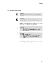
WARNING!
Risk of injury in case of insufficient qualification!
Improper working may lead to injury to persons and
damages to materials.
– Whatever activity may only be performed by persons
having the required training, the necessary knowledge
and the experience.
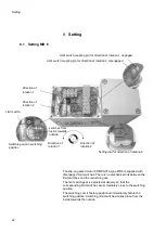
There is no general procedure for commissioning all three motors.
Connect the wires and the external control components such as
switches, contactors, fans, potentiometers, brakes, etc., according
to the attached wiring diagram.
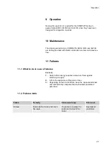
8.5 Overview of the switching ranges
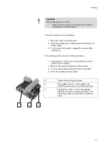
NOTICE!
If the motor stops and cannot be restarted any more, the
control and the direction of rotation do not match!
Cause: Two phases are inverted.
Measure: Reverse the phases. Now the switching screw
number and the numbers of the directions of rotation match.
Then turn the switching screw in the positive direction to
release manually the actuated safety limit switch. The motor
must be able to rotate in both directions.
The limit switch setting can then be carried out.
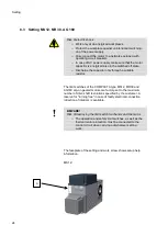
MS12
MR 30
AG60
Switching range


