25
English
they are available on output. Given the overall bitrate for an output MUX, determined according to the standard
and selected modulation parameters, the overall output band for the associated programs must be much lower,
otherwise the low priority programs will be lost or will not work properly.
After configuring the output mux parameters, the available band can be viewed in the web configuration
homepage or from the panel menu in the section OUTPUT -> MUX1 / MUX2 / MUX3 / MUX4 -> BITRATE.
Programs can then be added to the output mux until the overall peak band for the added channels exceeds the
mux band, as the excess band data that cannot be broadcast are rejected by the system.
Therefore, the installer needs to check that the maximum peak bitrate of the programs inserted does not
exceed the available band.
If the output band limit is exceeded, and for as long as it lasts, the system automatically chooses which programs
to broadcast according to the priority order, guaranteeing correct broadcasting of the high priority programs
(with a lower position number).
The first programs to be penalised are the low priority ones (with a higher positon number), which lose their
packages and are displayed as an error.
If the output band falls below the available band again, all the programs are broadcast without the loss of any data.
To facilitate this, the system offers a band graphic indicator in the web management, which is updated
automatically every second.
The length of the complete graphic bar (including the green, grey and white colours) shows the overall available
band for the output mux, while the band immediately used by the programs is green.
As the overall band of all the programs could change during time, the maximum acquired value since the last
reset (done by pressing RESET PEAK) is shown in grey.
If there is a white section, it shows the available bitrate and, therefore, the margin that can still be used. If at any
time a band peak reaches and exceeds the maximum, there is no white section and the red overflow led is lit.
The same values numerically are available in the OUTPUT -> MUX1 / MUX2 / MUX3 -> BITRATE section menu.
The second indication is in the input program list menu with 3 signalizations: the total bitrate will be given in red
with a yellow triangle and the low priority programs, that are discarded, will be written in red.
Therefore, the installer should configure the output program list, after being fully documented about the
maximum band required by each program (online or from technical literature) and monitor the total bitrate for
a sufficient period of time to make sure that the overall peak never reaches the maximum available, but that
there is always a minimum margin available to offset any problems that may occur.
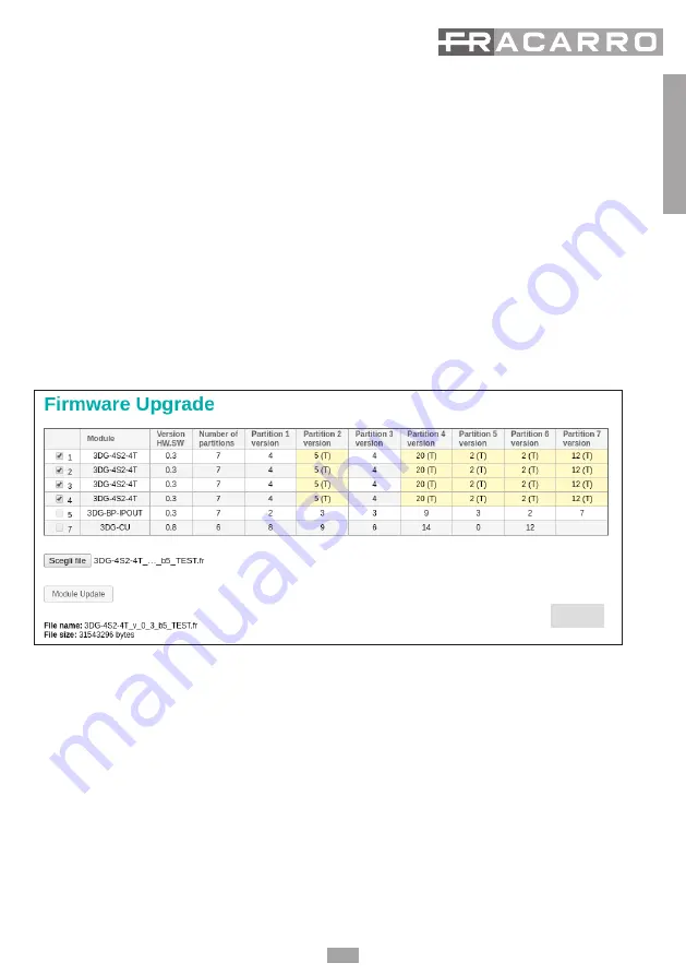
Fig 23
Содержание 3DG-4ASI-4T
Страница 1: ...3DG 4ASI 4T OPERATING INSTRUCTIONS...


